10. Timer Compare: Motor PWM
Important
The hands-on portion of this activity may be completed in groups of 2 students as an RSLK is required.
10.1. Purpose
This activity introduces the implementation and use of Timer Compare modules and their use in generating Pulse Width Modulation (PWM) to control wheel speed.
10.2. Hardware and Tools
RPI-RSLK Robotic Car
10.3. Description
This portion of the activity will serve as a guide to implement Pulse Width Modulation, or PWM, in order to control the RSLK drive wheels’ speeds. The motors on the car are connected through an H-bridge chip (DRV8838) such that no hardware needs to be built for this application. The connections on the RSLK are as shown in the figure below.

Wiring of motors on RSLK
The pins for Enable and Direction were of course initialized for use in Laboratory 1; where fixed speed control was built into the template project. The speed control for this activity and future laboratories must be implemented using two PWM outputs generated from a timer module, one for each wheel. While the DRV8838 and motors will work using a huge range of frequencies, for the purposes of this class a PWM period of 40 kHz should be used.
10.3.1. PWM Generation
See also
For a more thorough documentation on the Timer’s Compare mode, see the EmCon HAL documenation here: Compare mode.
Implementation of PWM is fairly straight forward as long as it is clear how to configure and use a timer in order to track time. PWM is generated by using a timer’s count to trigger an output to change value when a specific count value is reached. This additional functionality is supported by a TIM module’s Capture Compare Register, or CCRn; configured to operating in Compare Mode. A CCRn is capable of directly driving a linked GPIO pin, as opposed to requiring code to explicitly change the pin value, as described in the figure below. In this figure, the TIM module (specifically a TIMGx module as labeled) is configured to operate in Up Mode, where the value for Max is specified by the Up Mode configuration’s .period field.
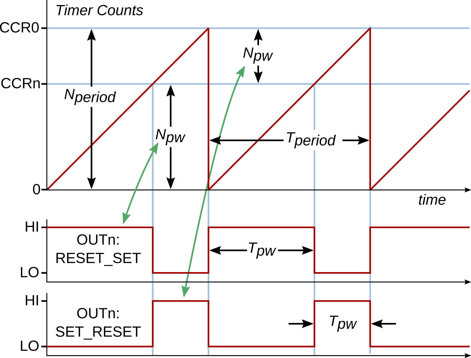
TIM Timer Up-Mode PWM behavior
As shown, a CCRn is configured in the Compare Mode (using the struct type Timers_CompareConfig) to generate the PWM output, denoted as the TIMGx_Cn signal. The figure shows two different variations on the generated PWM. The specific functionality is selected with the .action field values. Examples of that configuration for each variation is given below:
PWM type 1: Output is
SETonZEROevent andCLEARed onCOMPAREevent. *.action = TIMER_CCR_ACTION_ZERO_SET | TIMER_CCR_ACTION_UPCOMPARE_CLEARPWM type 2: Output is
CLEARed onZEROevent andSETonCOMPAREevent. *.action = TIMER_CCR_ACTION_ZERO_CLEAR | TIMER_CCR_ACTION_UPCOMPARE_SET
Once configured appropriately and the timer started, the PWM would be generated without intervenion; that is, the PWM signal will be continuously generated until the program instructs it to be changed or stopped. This implies that no timer interrupts are necessary to maintain said operation. To change the PWM duty cycle, a new value for the CCRn compare value must be computed and assigned to the CCRn via the function Timers_setCCRValue().
10.3.2. PWM Output Routing
As noted, the CCRn module will control an output signal TIMGx_Cn for a TIMGx module; where n corresponds to the CCR number. By default, this TIMGx_Cn signal is not passed to a GPIO pin. This is changed by configuring the applicable GPIO pin into an Alternate Function or Peripheral Function mode (GPIO Alternate Functions). It should be noted that each GPIO pin is capable of being linked to a small subset of the available signals to be routed; therefore, it is necessary that the correct GPIO pin is selected to support the generated output signal. Conversely, if PWM must be generated on a specific pin, as is the case with the RSLK, then the appropriate TIMG/TIMA module and CCRn must be configured to generate the PWM.
10.4. Instructions
This activity consists of three parts, where part 1 is a set of problems and part 2 and 3 are hand-on work:
LED manipulation via a timer output with frequency and duty cycle control and
Motor speed control via timer generated PWM.
Part 1 may be done before or after parts 2 and 3.
10.4.1. Part 1: Calculations
This portion of the activity must be done individually.
A PWM signal is generated with a duty cycle of 15% and a frequency of 1 kHz. What is the pulse width of the signal?
A 16-bit timer is used to create a PWM-type output with a timer increment time of \(T_\mathrm{TIMCLK} = 100~\mathrm{ns}\). The timer is in UP mode and is configured to set the output high on a compare event and low on a timer reset. The PWM period is set to 6 ms.
What maximum count value has the timer been configured to operate with?
Assuming a pulse width of 4 ms, what is the compare value?
The compare value from the previous question is halved. What is the new pulse width?
If the maximum timer count value was doubled after the previous subquestion, how does the pulse width, PWM frequency, and Duty Cycle change?
A timer operating with a period of 5 s is configured for a non-PWM output such that on a compare event, the output is set to toggle. What is the pulse width, frequency, and duty cycle of the generated output?
10.4.2. Part 2: LED Control
This portion of the activity may be done in groups of two.
Ensure the RSLK is on a foam block before powering on. This will prevent cars from driving off the benches and becoming damaged. It is possible that code programmed on the car involves the wheels starting as soon as the car is powered on.
Import a new
Template Projectand name it appropriately.Within a
GPIOInit()function, configure:Bumpers [BMP1,BMP2,BMP5,BMP6] for use (pins [PA7,PA14,PB23,PB25]).
PA0 (LED1) to be an controlled by signal TIMG8_C1.
Note
PA0 control of LED1 uses inverted logic: setting PA0 = LOW causes the LED1 to be ON, PA0 = HIGH causes the LED to be OFF.
Within a
timerInit()function:Initialize TIMG8 to use the LFCLK clocksource (32.768 kHz) and not BUSCLK, with a clock divider of 2,
Set the timer to use either UP or DOWN mode, and
Configure the timer to have an initial period of 1 second.
Create the initialization struct (type
Timers_CompareConfig) and populate the fields…
.ccrn: Select CCR1..action: Set this appropriately to produce a PWM. Note that either types as shown above are acceptable here..value: Set this value to be half the timer period..invertOutput: Set this to either value. Note that setting this to1would effectively cause the PWM type configured in.actionto be flipped.
Important
The CCRn action(s) selected for the
.actionfield must match the timer mode! For example, if using the timer in DOWN mode, then the CCRn action must be of the_DOWNCOMPARE_type. An_UPCOMPARE_type event would never occur!Apply the CCRn configuration with the function
Timers_initCompare(). This function must be called afterTimers_initTimer().And finally, start the timer.
Add
GPIOInit()andtimerInit()to themain()function at the appropriate place.Compile and test the code. LED1 should be blinking at a rate of 1 s if working correctly (on for 0.5 s, off for 0.5 s).
Within the
main()functionwhile(1)loop, check to see if each of the bumpers have been pressed and adjust the LED behavior accordingly:BMP1 Pressed: Increase blink frequency by 10 % to a minimum period of 0.1 seconds
BMP2 Pressed: Decrease blink frequency by 10 % to a maximum period of 2.0 seconds
BMP5 Pressed: Increase blink duty cycle by 10 % to a maximum of 100 %
BMP6 Pressed: Decrease blink duty cycle by 10 % to a maximum of 0 %
if(!GPIO_readPins(GPIOA,GPIO_PIN7)){ // BMP1 Pressed
    delay_cycles(320e3);
    while(!GPIO_readPins(GPIOA,GPIO_PIN7));
    delay_cycles(320e3);
    // Add code to increase blink frequency by 10 %
}
// Code for BMP2 (PA14)
    // BMP1 Pressed: decrease blink frequency by 10 %
// Code for BMP5 (PB23)
    // BMP5 Pressed: increase blink duty cycle by 10 %
// Code for BMP6 (PB25)
    // BMP6 Pressed: decrease blink duty cycle by 10 %
The most straight-forward way to complete the above is to create two variables to store both the timer period (or frequency) in seconds (or Hz) and duty cycle (0-100) and perform math on these, then update the timer. For example, to increase the timer frequency by 10 %, the following process could be used:
period -= 0.1*period; // same as... period *= 0.9
// Enforce limits on period (if below: set to minimum, if above: set to maximum)
// Math to convert "period" to timer period value (same as .period calculation)
Timers_setPeriod(...); // Update the timer's period
// Math to convert new "period" and "dutycyle" to CCR1 value
Timers_setCCRValue(...); // Update the CCR1 value to maintain duty cycle
Similarly, the duty cycle could be increased by 10 % like so:
dutycycle += 10; // duty cycle is stored as a percentage in this example
// Math to convert "dutycycle" to CCR1 value
Timer_setCCRValue(...); // Update the CCR1 value to maintain duty cycle
Note
As shown in the example processes above, both the timer period value and CCR1 (controlling the duty cycle) must be updated when the period changes. This is because the duty cycle is a function of the ratio between the period and CCR1 and not solely by the CCR1 value, where CCR1 actually controls the LED’s “pulse width” as described above, not the duty cycle directly.
Compile and test the code. If working properly, you should be able to adjust both the LED blink frequency and duty cycle independently.
Save the code to be submitted to the Gradescope assignment.
10.4.3. Part 3: Motor Speed Control
This portion of the activity may be done in groups of two.
Copy and rename the project from Part 1 OR import another
Template Projectand name it appropriately. If copying from part 1: most, if not all, code from Part 1 will be modified or removed. The LED1 functionality is not expected to persist in Part 2.Determine the required GPIO pins to output the PWM signal on (see motor schematic above). From this information, determine an appropriate TIMGx instance to use and the Capture Compare Register (CCRn) modules needed to generate the PWM on the appropriate pins. See here: GPIO Alternate Functions. Hint: there are two valid answers for which TIMGx instance to select.
Within a
GPIOInit()function, configure the necessary outputs:The Direction and Enable lines for each motor must be configured as normal outputs. Set these outputs to both enable the motors and set the direction to forward.
Note
The motors will travel in the “forward” direction if the DIR pin is set to low.
The PWM outputs must use the necessary alternate function configurations as described here: GPIO Alternate Functions
All bumpers [BMP1-BMP6] for use (pins [PA7,PA14,PB5,PB21,PB23,PB25]).
Within a
timerInit()function, initialize the selected TIMGx instance such that it resets at the desired PWM frequency (40 kHz) using BUSCLK and a clock divider of 1. UP or DOWN mode may be used. No interrupts are needed.Note
The period required for this timer 1/(40 kHz) is much smaller than any other period generated in the course so far. As such, it would make sense to use a much smaller divider on BUSCLK (e.g., /1) to generate the timer input clock in order to allow for higher resolution PWM; that is, have more timer counts in one reset period, allowing for more flexibility and finer control of changes in setting of the PWM duty cycle.
Also within
timerInit(): configure the applicable CCRn modules to generate PWM. Note that theTimers_CompareConfigstruct allows for multiple CCRs to be configured at once. Set both CCRn initial values to produce 10 % duty cycles (motors are rotating slowly).Start the timer within
timerInit()after all configurations have been applied.Add
GPIOInit()andtimerInit()to themain()function at the appropriate place.Within the
main()functionwhile(1)loop, check to see if each of the bumpers have been pressed and adjust the motor behaviors:BMP1 Pressed: Increase the left wheel CCRn compare value by a value \(N\)
BMP2 Pressed: Decrease the left wheel CCRn compare value by a value \(N\)
BMP3 Pressed: Toggle the direction of the right wheel
BMP4 Pressed: Increase the right wheel CCRn compare value by a value \(N\)
BMP5 Pressed: Decrease the right wheel CCRn compare value by a value \(N\)
BMP6 Pressed: Toggle the direction of the left wheel
where the value for \(N\) is set such that it is one-tenth of the your calculated \(N_{period}\) (the number of counts in the timer period).
The setup for this button press logic could follow the same procedure as used in Part 1: here.
In addition to the above, ensure that whenever a compare value is being updated that its duty cycle stays within the range 10 % and 90 %:
if new compare value is > 90 %
    Set new compare value to be 90 %
if calculated compare value is < 10 %
    Set new compare value to be 10 %
apply compare value to CCRn with Timers_setCCRValue()
Test the code. If operating correctly, the user should be able to cause the left and right wheels to accelerate/decelerate and flip directions independently of the other.
Important
Remember that the car needs charged batteries and must be on for the motors to run. The USB cable only powers the Launchpad Board and the components directly connected to it (e.g., the LEDs). The Blue LED near the power button must be lit brightly. The car batteries must be replaced/added if the LED does not light, is lit dimly, or the Red low-battery LED light (next to the blue power light) illuminates when the power switch is on and motors are “running”.
If desired, the car may be unplugged from the computer and placed on the floor to test. Likely: it will be seen that the car does not travel in a straight line but instead turns with a gradual arc.
Submit both Part 1 and Part 2 codes to the Gradescope assignment.