11. Timer Capture: Motor Encoders
Important
The hands-on portion of this activity may be completed in groups of 2 students as an RSLK is required.
11.1. Purpose
This activity introduces the implementation and Encoders to measure wheel speed and drive distance via Timer Capture functionality.
11.2. Hardware and Tools
RPI-RSLK Robotic Car
11.3. Description
PWM speed control of the motors on the RSLK works well but the control is not accurate with respect to absolute speed. This causes there to be a slight speed difference between the left and right motors on the car as they are independent drives; causing the cars to turn or drive along an arc when motors are receiving equivalent pulse widths. Therefore, it is useful to have a measure of the actual speed of the motors in order to adjust the PWM as necessary to achieve the desired speed. This functionality will not be accomplished in this activity but will instead be completed in Laboratory 3.
This activity guides through implementing a timer to Capture the motor speed and distanced traveled; which is indicated by an attached magnetic encoder. A Hall effect sensor produces a digital signal corresponding to the rotation of the magnetic encoder. The RSLK has two Hall effect sensors per encoder/wheel, providing two digital outputs per side:
The two sensor locations are noted as the green and yellow marks as shown in the animation above. The outputs of said sensors are provided in the plot on the right as the wheel rotates. The rotating red/blue disk is the magnetic encoder rotating with the DC motor. It is clear that the encoder is rotating much faster than the wheel: the motor/encoder are connected to the wheel through an effective 60:1 gear train and a 6-pole magnetic disc; resulting in 360 encoder cycles per wheel rotation. For purposes of demonstration, the video above shows a gear train of 10:1 and a 1-pole magnetic disk.
Only one hall effect sensor is required to measure the wheel speed; two are included to support detection of spin direction. Measurement of direction is not required in this activity.
Measurement of speed can be accomplished by tracking the timing between the rising and/or falling edges of the sensor output. This, of course, can be supported by a TIMG or TIMA instance; this time using the Capture Mode.
11.4. Timer Capture Description
The TIMG/TIMA functionality behaves akin to the Compare Mode (used to generate PWM) but in reverse: instead of producing external events when the timer reaches a certain value, the Capture mode uses an external event to cause the CCRn to save the current timer value. The external signal is the same as used for the compare mode: TIMGx_Cn. This functionality is described in the figure below.
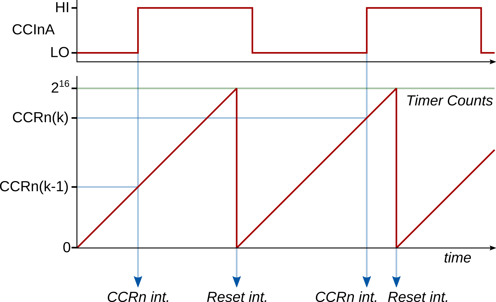
TIMGx capture operation in continuous mode, triggering on rising edge of TIMGx_Cn.
In this instance, the TIMGx module is set to count in UP mode with the period set to its maximum: 65535. This provides for the largest sample period range, allowing for fewer timer resets during each measurement (more efficient). It is possible to perform the same functionality with UP-DOWN mode to further reduce timer resets; however, the math becomes more complicated.
When an external event occurs on TIMGx_Cn, triggering a timer compare, the current count value is stored within the CCRn attached to the external signal. Both rising and falling edges may be used to trigger the compare event. These events may be directly used to calculate distance traveled for a wheel: each event indicates a rotation of 1/360 of the wheel circumference since the last event (rising-to-rising or falling-to-falling); therefore, counting the events effectively serves as a distance measurement. Likewise, the speed of the rotation may be calculated through the time difference between the events.
Measuring the time difference between two capture events that happen within the same timer period is straight forward: subtract the difference between the captured timer counts and calculate the time knowing the timer clock:
where \(\mathrm{CCRn}(k)\) is the timer capture value for sample \(k\), and \(f_\mathrm{TIMCLK}\) is the timer clock.
This becomes slightly more difficult when the events span across timer reset periods. For example, if the timer resets once between capture events, then the calculation becomes:
where \(2^{16}-\mathrm{CCRn}(k-1)\) is the number of counts between the previous capture event and the ZERO event.
This math can be extended to multiple resets between capture events by simply adding \(2^{16}\) for each reset that has occurred, leading to:
where \(N_\mathrm{resets}(k)\) is the number of timer resets that have occurred between two capture events.
11.5. TIMG/TIMA Capture Implementation
As noted above, the timer instance should be set up to count its maximum period. A fast count frequency is desirable to provide the highest resolution accuracy to the timer measurement; therefore, the timer clock divider is typically set small, e.g., \(N_\mathrm{div} = 1\).
With the timer instance configured for as above mode, the CCRns may be configured to support Capture Mode. This is done by creating a Timers_CaptureConfig struct and populating the fields appropriately. Make sure to read the description for each field as provided in the linked documentation: some fields should always take the same value. Some additional notes:
A capture event must be acted upon in a timely manner. Therefore, it is necessary to enable the associated interrupt for each CCRn used in capture mode.
Likewise, the number of timer resets must be tracked as well. This requires that either the ZERO or LOAD interrupt sources be enabled as well.
It does not matter which encoder edge is selected to trigger the capture event; however, both edges should not be used together (at least for this course).
Within the timer interrupt, several things must be tracked:
The number of timer resets since the last compare event: this is necessary to support calculation of the time between successive compare events,
The timer value of the last compare event: this is also required to calculate the time between successive compare events,
The total number of compare events: to track total rotation or distance.
Using these quantities, the time difference between successive compare events may be calculated from this equation.
Note
As you will see by the instructions below, these three points are incorperated, but the actual implementation does not use independent variables for the first two points; it is condensed into one counter variable.
11.6. Instructions
This activity is two parts. Part 1 is a set or problems and part 2 is hands-on work. These may be done in any order.
11.6.1. Part 1
This portion of the activity must be done individually.
A 16-bit timer is configured to capture falling-edge events with \(T_\mathrm{TIMCLK} = 0.1~\mathrm{\mu s}\) and timer reset period is set to its maximum possible value. 5 successive events are captured, where each captured CCR value and total number of timer resets since the timer was started were recorded, as given in the table below. What is the average time between events?
Capture Events for Question 1 Event
CCR Value
Total Timer Resets
1
42566
105
2
14092
109
3
55183
115
4
8176
118
5
39252
124
The same timer as used above is reconfigured to produce both rising- and falling-edge events in order to measure a PWM input signal’s characteristics. Given the sequence of events as given below, what is the pulse width, period, and duty cycle of the PWM signal?
Event History for Question 2 Event
Event Type
CCR Value
1
Zero
–
2
Falling Edge
22531
3
Zero
–
4
Zero
–
5
Rising Edge
29059
6
Zero
–
7
Falling Edge
39123
8
Zero
–
9
Zero
–
10
Rising Edge
45651
11
Zero
–
12
Falling Edge
55715
13
Zero
–
11.6.2. Part 2
This portion of the activity may be done in groups of two.
The following instructions will guide you towards configuring the RSLK to be used as a crude “tape measure”, where the RSLK is manually pushed over a distance to measure. Only one of the RSLK motor encoders will be used.
Import a new
Template Projectand name it appropriately.Create a
GPIOInit()function and initialize one of the pins (RPI-RSLK Pin Mapping: PB10 for left wheel encoder or PB11 right wheel encoder) to the appropriate Alternative Function. Take note of the selected TIM instance number and CCRn register required for the pin selected.Important
These is more than one timer option to use with the encoders on PB10 and PB11. While any will work, the timer that was used in the previous activity should not be selected as they will both be used in upcoming labs.
Create a
timerInit()function and initialize the required timer instance:The timer should use UP mode.
The timer should be using a divider of 1.
The period should set to its maximum.
Apply the configuration with
Timers_initTimer().
Still within
timerInit()and afterTimer_initTimer(): configure the required CCRn for capture mode using the struct typeTimers_CaptureConfig.The input selection field (
.inputSel) should beTIMER_CCR_INPUT_CCPnto select the correct input. Note that thenin this case is not replaced with a number.All other fields are needed and must be specified.
Apply the configuration with
Timers_initCapture().
Enable two interrupts sources and the actual CPU interrupt. The interrupt sources should be:
Either the ZERO or LOAD interrupt source, and
The CCRn interrupt source, triggered on a capture event when the timer is counting in UP mode.
Finally, start the timer towards the end of
timerInit().Create four global variables, one each to:
uint32_t enc_total_eventsKeep track of total encoder events, useful in measuring distance traveled.int32_t enc_counts_trackKeep track the timer counts since the capture event (must be signed!).int32_t enc_countsFinal value of timer counts between capture events.uint8_t enc_flagA flag to denote that a capture event has occurred.
Create the corresponding timer
_IRQHandler()interrupt function. Within this function, implement the following pseudocode:Check to see if timer reset interrupt has occurred. If yes: Clear the reset interrupt flag Add 65536 (=2^16) to enc_counts_track Check to see if a capture event ocurred. If yes: Clear the capture event interrupt flag Increment enc_total_events (total number of capture events that have occurred) Calculate enc_counts as enc_counts_track + capture value Set enc_counts_track to -(capture value) Set enc_flag to 1
Note
Comments on the pseudocode above:
Use
Timers_getActiveInterrupt()orTimers_getPendingInterrupts()to check which interrupt event(s) has occured.Clearing of interrupt flags is only necessary if using
Timers_getPendingInterrupts()
The math for
enc_countsandenc_counts_trackis taken directly from the numerator of this equation. The equation is built piece-by-piece:enc_counts_trackis set equal to \(-\mathrm{CCRn}(k-1)\) (second to last line of pseudocode).Each timer reset is added into
enc_counts_trackone-by-one (\(65536 N_\mathrm{resets}(k)\))The most recent count value, \(\mathrm{CCRn}(k)\), is combined with
enc_counts_trackto produceenc_counts.
Refer to Timer Interrupt Handling for the functions to check and set the interrupt flags.
The capture value may be obtained using the function
uint16_t Timers_getCCRValue(), documented here.
Just prior to the
main()functionwhile(1), add the print statement:printf("\r\nDistance\tEnc_Counts\tDelta T\t\tAng.Speed\tLin.Speed\r\n"); // Column headers printf("\r\nDistance\tEnc_Counts\tDelta T\t\tAng.Speed\tLin.Speed\r\n"); // Column headers
Within the
main()functionwhile(1), add the segment of code:if(enc_flag){ // Check to see if capture occurred enc_flag = 0; // reset capture flag uint16_t distance = ... ; // Calculate distance travelled in mm using enc_total_events float delta_t = ... ; // Calculate the time between previous and current event using enc_counts float speed_rpm = ... ; // Calculate the instantaneous wheel speed in rpm float speed_mm = ... ; // Calculate the instantaneous car speed in mm/s printf("%5u mm\t%8u\t%7.1f ms\t%5.2f rpm\t%5.2f mm/s\r\n",distance,enc_counts,delta_t*1000,speed_rpm,speed_mm); }
Finish the calculation for
delta_tvariable, which is the time measured between the previous and current encoder events. Note that the numerator for this equation was generated within the interrupt routine asenc_counts.Finish the calculation for the
distancevariable. Each compare event corresponds to 1/360 of a wheel rotation. You must measure the wheel diameter or circumference.\[c = 2 \pi r\]Finish the calculation for the
speed_rpmvariable. This is an instantaneous value that should be calculated from just theenc_countsvariable, knowing there are 360 compare events for each full rotation. rpm is revolutions per minute.\[\omega\left[\mathrm{rpm}\right]= \frac{1}{360}\frac{1}{\Delta t}\frac{60~\mathrm{s}}{1~\mathrm{min}}\]Finish the calculation for the
speed_mmvariable. This is an instantaneous value in mm/s that should be calculated from theenc_countsvariable and the wheel dimensions.\[v = \omega\left[\mathrm{rad/s}\right] r = \frac{2 \pi}{360}\frac{1}{\Delta t} r\]Test the code by pushing the car GENTLY across the table surface. Be careful to not touch the encoders while pushing the car as it may break the gear train or cause the clutch to slip. Verify the terminal output of distance by measuring the distance traveled.
Take a screenshot of the terminal output after the RSLK has been pushed some distance. Submit this screenshot and the final code to the corresponding Gradescope assignment.