Software Installation
This page contains instructions to install and test the software required for ENGR-2350.
1. Code Composer Studio Installation
Code Composer Studio (CCS) is a free integrated development environment (IDE) that is designed to be used with Texas Instruments products. Please follow the instructions below to install. These instructions describe the process within Windows; however, the process within Linux or MacOS should be similar.
Download the CCS installer for your OS from the TI website: CCSTUDIO Downloads
On this page, select Download options to the right of CCSTUDIO.
Download the applicable installer. Note that this download is large (>1.0 GB).
Extract and run the installer.
Click Next as needed until it starts the download and install process. You generally can accept the default options unless noted below:
Of course you need to accept the license in order to continue.
You may change the installation directory if desired. The default is fine.
Ensure that Custom Installation (Recommended) is selected when applicable.
On the Select Components view, select only the item MSPM0 Arm® Cortex®-M0+ microcontrollers.

Note
The installer may present slightly different dialogs on different OSs. No additional configuration changes than those listed above are needed for Linux or MacOS; therefore, any additional options may be ignored.
The install process will take a several minutes.
2. MSPM0 Software Development Kit (SDK) Installation
In addition to CCS, the SDK for the microcontroller used in this class also needs to be installed. This may be done directly through CCS following the instructions below.
First, launch CCS.
Open the Resource Explorer. This may be done through View → Resource Explorer.
Within the Resource Explorer, expand the Arm®-based microcontrollers folder on the left pane, open the subfolder Embedded Software, and select MSPM0 SDK - 2.##.##.##.

Click Download and Install on the top-right of the right pane.
You will be asked to confirm the installation of the SDK along with another packages, SysConfig. Proceed with the installation with the default selections.
Again, the install process will take several minutes. The progress can be monitored with the Resource Explorer (a small busy icon will appear).
Verify that the install completed. Navigate again to the Resource Explorer and the MSPM0 SDK - 2.##.##.## item. If the item has a check next to it, all is good and you may move on. If it does not, click Downlaod and Install again and repeat the process noted above.

3. Test Project
To ensure that the installation worked properly and the computer can program the evaluation board or robotic car, we will attempt to load a test project onto the target:
Download the project archive from here:
TestProject.zip.Extract the zip archive to a temporary location. This location should be accessible but it is not important where. When imported into CCS, it will be copied into the current workspace folder and the extracted version is not used.
Select File → Import Project(s)… from the CCS Menu.
In the Import dialog, select the folder where you extracted the project:
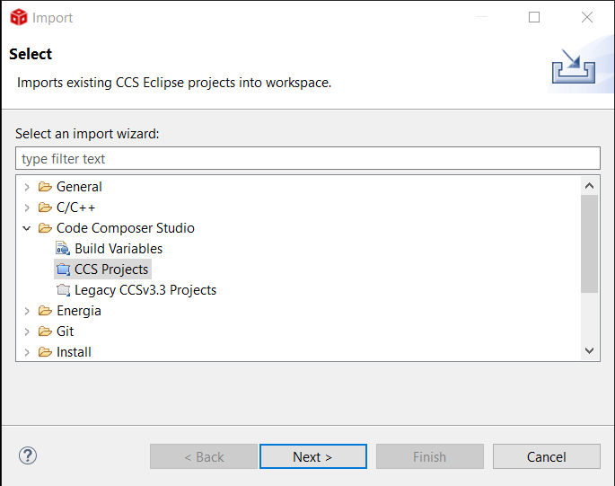
Select the project from the listed Discovered projects and click Finish to import the project.
Attention
If a project with the same name as the project to import already exists in the workspace, the dialog will prevent another import. You must first rename the project in the current workspace to be able to import another copy.
Click Finish to import the project into the workspace.
Upon success, this should result in the project being visible in the EXPLORER pane. If this pane is not visible, it may be shown by going to View → Explorer or selecting the Explorer icon on the left toolbar.

The test project code may be considered a complete program; that is, no modifications are necessary for it to run. However, it should be ensured that the program can be compiled successfully. To compile the project:
First, ensure that the necessary toolbar is visible. If the toolbar shown below is not visible, enable it via View → Toggle Toolbar.

Next, click the button on the toolbar that resembles a hammer and screwdriver crossed:
 , by Project → Build Project(s), or by pressing the CTRL+B shortcut.
From the menu: Project → Build Project,
The Console pane will show the progress of the compilation. If all goes well, the console should read something similar as shown below:
...
Building target: "TestProject.out"
Invoking: Arm Linker
"C:/ti/ccs2020/ccs/tools/compiler/ti-cgt-armllvm_4.0.3.LTS/bin/tiarmclang.exe" -march=thumbv6m -mcpu=cortex-m0plus -mfloat-abi=soft -mlittle-endian -mthumb -O0 -D__MSPM0G3507__ -gdwarf-3 -Wl,-m"TestProject.map" -Wl,--heap_size=0x800 -Wl,-i"C:/ti/mspm0_sdk_2_05_01_00/source" -Wl,-i"C:/Users/Wilt/workspace_ccstheia/TestProject" -Wl,-i"C:/ti/ccs2020/ccs/tools/compiler/ti-cgt-armllvm_4.0.3.LTS/lib" -Wl,--diag_wrap=off -Wl,--display_error_number -Wl,--warn_sections -Wl,--xml_link_info="TestProject_linkInfo.xml" -Wl,--rom_model -o "TestProject.out" "./main.o" "./inc/startup_mspm0g350x_ticlang.o" "./src/engr2350_gpio.o" "./src/engr2350_mspm0.o" "./src/ti_msp_dl_config.o" "../inc/mspm0g3507.cmd"  -Wl,-l"C:/ti/mspm0_sdk_2_05_01_00/source/ti/driverlib/lib/ticlang/m0p/mspm0g1x0x_g3x0x/driverlib.a" -Wl,-llibc.a
Finished building target: "TestProject.out"

**** Build Finished
Attention
If instead of the above output you receive the error message below within the console, the steps in 2. MSPM0 Software Development Kit (SDK) Installation were not completed successfully. Revisit those steps as needed.
Buildfile generation error occurred..
Product MSPM0-SDK v2.5.1.00 is not currently installed and no compatible version is available. Please install this product or a compatible version.
Build stopped..
Note
The remaining steps require either the Launchpad Board or RSLK.
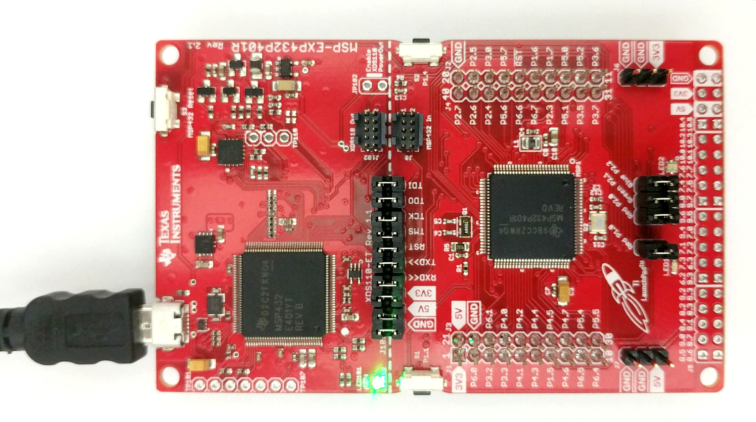
Before proceeding within CCS, the development board must be connected to the computer. When connected, the board will have a green LED (LED102) lit constantly. LED1 may also be blinking RED, depending on the default firmware of the microcontroller.
It is suggested that you use the micro-USB cable provided with the development board to connect to the computer; however, all other micro-USB data cables will work just fine. If the steps below do not work properly with a different cable, ensure that the cable used is not strictly a power cable.
With the board connected, the project can be downloaded and run. For this class, we will always do this through “Debugging”. To start debugging:
By clicking the button on the top toolbar that resembles a green beetle:

From the menu: Run → Debug Project,
Pressing the keyboard shortcut F5.
Note
If more than one project is in the workspace, care must be taken to ensure that the correct project is debugged! CCS may launch a different project then the one intended.
Initiating the debug interface will cause the project to be compiled (turned into a program) if not done so already and loaded onto the microcontroller. The first time this is done for the development board will likely trigger a request for programmer firmware update. This should be agreed to.
Once the program has been loaded onto the microcontoller, the toolbar will change to show run controls. Further, the left pane may be changed automatically to the Debug view, which has the same controls.

To run the code, click the Continue toolbar button,
 (F5). This should cause LED1 on the development board to blink at a steady rate.
To ensure that changes to the code will be reflected in the downloaded program, modify line 57 within main.c from:
for(i=200000; i>0; i--);
to:
for(i=1000000; i>0; i--);
Once the code is changed, debug the program again (
) to recompile and download the program, initiating a new debug session. Alternatively, if you simple recompile () the code, CCS will ask if you want to load the new version of the program in the current debug session. The latter method is slightly faster, especially if Remember my decision is selected.Run the program:
.
Hint
The “debugger” that we are using is a powerful set of tools that this course will barely scratch the surface of. However, students should be aware of the functionality of these toolbar buttons as well:
 Pause the running program (F6). This will halt the execution of the code at its current point, which will be indicated by a yellow arrow,
  , to the left of the line of code. The code then may be resumed again by .
 Stop debugging (Shift+F5). This will disconnect the current debug session from the microcontroller but will not stop the code from running. Pressing this will require that a new debug session be started ().
 Restart the code from the beginning (Ctrl+Shift+F5). This button is very useful to quickly test a program multiple times without having to repeatedly press (much slower).
4. Serial Terminal
We will be using a serial terminal emulator to interact with the microcontroller when a program is running. Code Composer Studio has a built-in serial terminal emulator which provides all necessary functionality except a logging capability to automatically save output to a file. Alternatively, an external program may be used, which will be dependent on your operating system. See below for the suggested programs for each OS. Note that there are many programs capable of performing this task and if you are comfortable with a different one, feel free to use it instead.
An active connection is only possible with the development board attached to the computer. If the board is removed and reattached, the serial terminal connection must be reestablished.
To test the serial terminal connection, the Test Project may be run again.
All OSes - CCS Serial Console
The CCS Serial Console is a basic terminal built into CCS. As it is built-in, installation is not required and connection is fairly straight forward:
Open the Serial Console view by finding it within the View → Console menu.
This will create a new Serial Console pane and/or tab in the CCS window. To connect to the development board, click the Connect/Disconnect COM Port
 button on the top-right of the pane to show the COM Port dialog:
Determine and select the correct serial port to select. Instructions for determining the correct serial port are provided in Finding Serial Port.
Ensure that the remaining options match those provided below (and in the figure above).
Baud Rate: 115200
Parity: None
Data Size: 8
Stop Bits: 1
Click “OK”.
As noted, a logging feature is not available within the CCS Terminal. If the data printed needs to be saved, it is possible to simply copy and paste the required text into a text file.
Important
A common issue when debugging is that students may open the Serial Console pane but forget to create the connection. Remember to connect the terminal!
Finding Serial Port
The development board presents itself as two independent serial port devices, among others that may exist. Determining the appropriate name or path for the serial port is dependent on the OS.
Windows
See also
Ensure that the development board is connected to the computer.
Open the Windows Device Manager.
Under Ports, find the entry XDS110 Class Application/User UART (COMx). The cooresponding COMx name and number is the required serial port. This value may change when the device is remove and readded to the computer, though if plugged into the same USB port, it usually will stay the same.
Linux
Determining the serial port on Linux can be done several ways. Here are two:
Using
dmesg:Prior to plugging the development board in, run
dmesgin the follow mode:
$ dmesg -w
Plug the development board into the computer. This should result in a
dmesgoutput of something along the lines of this:
usb 1-4: USB disconnect, device number 27
usb 1-4: new full-speed USB device number 28 using xhci_hcd
usb 1-4: New USB device found, idVendor=0451, idProduct=bef3, bcdDevice= 1.00
usb 1-4: New USB device strings: Mfr=1, Product=2, SerialNumber=3
usb 1-4: Product: XDS110 (03.00.00.07) Embed with CMSIS-DAP
usb 1-4: Manufacturer: Texas Instruments
usb 1-4: SerialNumber: M4321005
cdc_acm 1-4:1.0: ttyACM0: USB ACM device
cdc_acm 1-4:1.3: ttyACM1: USB ACM device
hid-generic 0003:0451:BEF3.000E: hiddev1,hidraw2: USB HID v1.11 Device [Texas Instruments XDS110 (03.00.00.07) Embed with CMSIS-DAP] on usb-0000:00:14.0-4/input5
Determine the target serial port from the
dmesgoutput: The lines of interest are highlighted above. The board provides two serial ports when connected; in this case, these are ttyACM0 and ttyACM1. The correct one is the one that is listed first. Therefore, for this case: ttyACM0 is the target serial port. The full path to this port is/dev/ttyACM0
Directory listing:
Prior to plugging the development board in, list the contents of the
/dev/directory looking for any entries that start with eitherttyACMorttyUSB:
$ ls /dev/tty{ACM*,USB*} 2> /dev/null
Take note of the any entries listed from the output of this command. These are the existing serial ports.
Plug in the development board and run the above command again.
Two new entries should appear in the output. Select the lowest numbered new entry as the target serial port.
Note that the target serial port will not change upon removal and reconnection of the development board as long as:
A different device that presents itself as a serial port was added to the computer, or
An active serial terminal session was not exited at reconnection.
Therefore, the device determined above may generally be used for all subsequent connections.
MacOS
The correct port for MacOS seems to be generated directly from the device hardware and/or product IDs, and is usually listed as /dev/cu.usbmodemM43210051. If this is not listed as an available port, select the lowest numbered /dev/cu.usbmodemM432 device.
Windows - PuTTY
Warning
Installation of PuTTY is only necessary if not using the built-in terminal within CCS. If using the CCS built-in terminal, ignore the instructions below.
Installation
Download the most recent version of PuTTY from the PuTTY Downloads page. Either the MSI Installer or just putty.exe will work. The 64-bit x86 version is the applicable version for almost all Windows based computers.
If the MSI Installer was selected, follow the installation instructions. This version will place the PuTTY program (among others: PuTTYgen, PSFTP, etc.) within the Windows program menu.
If using putty.exe, it is highly suggested to pin the program to the taskbar to make accessing the program easy and quick.
Connecting
Launch PuTTY. If installed using MSI Installer, select the PuTTY application from the program menu and not PuTTYgen, PSFTP, etc.
In the window that appears, do the following:
Select the Serial radio button near the upper right, not the “Serial” option on the bottom left.
Change Speed to 115200.
Change Serial line to the necessary COM port as determined by Finding Serial Port.
Click Open. This will launch a terminal session if configured properly.
If the development board was removed and reconnected, the terminal session may be restarted by right clicking the PuTTY window title and selecting
Saving Settings
PuTTY can save a session configurations to avoid having to repeat the above steps each time. However, it is possible that the COM port will not be consistent across different sessions. To save settings:
Complete the Connecting instrutions above up to step 2.
Type a name into the Saved Sessions box.
Click Save on the right.
A new item will appear with the name provided in the Saved Sessions box below.
Loading Settings
There are two options here:
Double-click on the saved settings that are desired. This will automatically start the terminal session using these sessions.
Single-click on the saved settings that are desired.
Click Load
Change any settings (such as the desired COM port)
Click Open.
Logging Output
Logging of PuTTY sessions is useful in cases where the data needs to be saved. To do this: 1. Prior to launching the session, click Logging under Session on the left after loading/configuring the settings. 2. Change Session logging to Printable output. 3. Select the file to save the output to under Log file name. 4. Change any other settings here as desired. Note that these logging settings will be saved with the saved settings mentioned above. 5. Click Open to launch the logged session.
Linux – picocom
picocom is a small command line program to support serial connections.
Warning
This step is only necessary if not using the built in Terminal within CCS.
Installation
Use your distribution’s preferred method for installing programs. This is a common program and should exist in most distribution repositories. For example, if using apt (command line):
$ sudo apt install picocom
Connecting
Determine the target serial device via the instructions in Finding Serial Port.
Launch picocom to connect to the target serial device with a baud rate of 115200. Note that the full path to the target serial port is required. For example:
picocom -b 115200 /dev/ttyACM0
To exit picocom, either close the active terminal window or press Control+a followed by Control+q.
Logging Output
Logging of picocom sessions is useful in cases where the data needs to be saved. To do this, add the logging flag and a target filename, -g LOGFILENAME to the command:
picocom -b 115200 /dev/ttyACM0 -g test.log
MacOS - ????
Warning
This step is only necessary if not using the built in Terminal within CCS.
No instructions here. Instructors don’t use MacOS!