14. I2C Sensors
Important
This activity may be completed in groups of 2 students.
The lab only has a limited number of I2C sensors. Please return them or leave them on the RSLK when done.
Danger
This activity uses the 5V power available on the Launchpad Board and RSLK. Failure to follow the instructions may result in irreversable damage to the MSPM0G3507 as the pins are not 5V tolerant. Do not modify circuitry when the RSLK is powered or the Launchpad Board is plugged in.
Note
This activity uses the terms Controller and Peripheral in place of the historically used names Master and Slave. You should understand that the terms are synonymous in this context. Other naming conventions may also be seen in slightly different contexts, such as “primary/secondary,” “leader/follower,” or Python’s recent change to “parent/worker.” See here for more information: oshwa.org. Note that this link discusses changing the SPI protocol naming convention; this change is carried over to the I2C as well.
14.1. Purpose
This activity guides groups through configuring the MSPM0G3507 to interface with I2C sensors.
14.2. Hardware and Tools
RPI-RSLK Robotic Car or LP-MSPM0G3507 Launchpad Development Board
CMPS12 Electronic Compass Module, “Compass”
SRF08 Ultrasonic Range Finder, “Ranger”
2x Resistors (5 kΩ - 10 kΩ)
14.3. Description
Activities 11 and 12 both introduced methods for acquiring analog-type measurements from different input types: time-modulated digital signals and analog voltages, respectively. It is also common to have a digital sensor as part of an embedded system; where the sensor uses an ADC, Timer Capture, or other mechanisms to acquire analog-type data. Once the digital sensor acquires this data, it is necessary to transfer the measurement to the microcontroller. This can, of course, be extended to other types of digital components, where bits or bytes need to be transferred between two, or more, devices. For example, a microcontroller may be using an external memory module to provide data logging capabilities.
There is a plethora of different mechanisms with which two devices can communicate with each other (e.g., WiFi, Cellular, Ethernet, USB, etc.). All of these communication methods may be categorized as one of two types: serial or parallel communication; where serial communication sends one bit at a time, sequentially, and parallel communication sends multiple bits at a time. For the purposes of two devices (typically “chips”) in a compact embedded system, a simplistic serial protocol is usually more than sufficient to transfer the required data. These protocols include Universal Asynchronous Receiver-Transmitter (UART), Inter-Integrated Circuit (I2C), and Serial Peripheral Interface (SPI). For this class, we will focus on using I2C.
Note
The I2C protocol is also a subset of the System Management Bus (SMBus) protocol. Although there are differences between I2C and SMBus, for this course these protocols are effectively the same and can be used interchangeably.
The I2C protocol uses two signal lines; Serial Clock, or SCL, and Serial Data, or SDA; to provide the link between the devices, as shown in the figure below. Note that all devices (including the controller) are connected in parallel in this protocol, where SCL and SDA are shared between all devices. In addition to the device connections, two “pull-up” resistors are added, one connected to each signal and a DC voltage source. No matter how many peripherals are on the bus, there is always one resister per line. These are required as each device is only capable of pulling a signal low and cannot actively push the signal high. This GPIO configuration is known as Open-Drain. As all components are implemented with open-drain, the resistors are necessary to force the SCL/SDA to a high state when all devices are in an open state; that is, the line is not connected to ground or power within the device (the drain state). The values of these resistors are typically large (e.g., 2 kΩ < R < 50 kΩ).
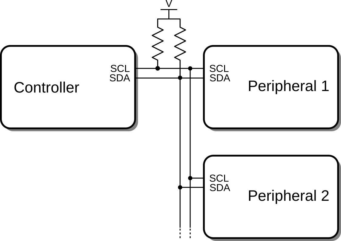
I2C hardware architecture
The controller does exactly what the name implies: it controls the I2C bus; indicating which device is sending/receiving data, when the data is transmitted, and how fast it is transmitted. The controller selects a peripheral to interact with via the peripheral’s address; a unique 7-bit number which identifies the peripheral on the bus. An 8th bit, the R/W bit, is added to the address to indicate whether the peripheral should be written-to (R/W = 0) or read-from (R/W = 1). Each transaction, or message, between the controller and a peripheral can only be a write or a read, there is no dual purpose transaction.
Writing to a peripheral usually requires that the controller indicate to the peripheral what it is writing; for instance, a configuration byte or a measurement trigger. This is done via the second byte sent in a write transaction indicating the start register (where a peripheral register is an accessible memory location on the periperal corresponding to a specific function). The next byte (3rd) sent in the message is written into the start register location. Any additional bytes sent would be written into the next sequential registers within the peripheral.
All bytes sent in a write must be acknowledged (ACK) by the peripheral, which is a single bit bus condition.

Write message packet structure. Blue is sent by the controller, red is sent by the peripheral.
Reading data from a peripheral follows a similar path of events as described for the write transaction. The read transaction again starts with the address plus R/W bit. The next data byte transferred is transmitted by the peripheral and read by the controller. Likewise, any additional bytes sent are also sent from the peripheral to the controller. The read transaction has no mechanism for the controller to request specific data (controller only sends address+R/W byte). Therefore, this must be started with a write message: a write message is used to send the start register but no associated data prior to a read message. This sets the “active” register in the peripheral to be the desired register to read from first, as specified by the start register. After the write message, a read transaction may be started, which will the first data byte containing the current value of the start register, the following bytes would be start register+1, start register+2, etc.
The byte acknowledgements during a read are generated mainly by the controller, except for the initial transmission of the address+R/W byte. A read also ends with a not acknowledgement (NACK) followed by the STOP condition. Note that the bus conditions of START, ACK, NACK, and STOP may be considered single bit; more accurately, they are signified by levels and transitions on the SDA and SCL lines.

Read message packet structure. Blue is sent by the controller, red is sent by the peripheral.
14.3.1. I2C Implementation
The I2C bus may be implemented using the I2C module. Both Register and TI DriverLib implementations of the I2C modules are complex and require many steps, namely in producing the write and read messages. For this course, two higher-level functions are provided to make the implementation quicker and easier:
void I2C_writeData(...): produce an I2C write transaction.
void I2C_readData(...): produce both an I2C write and read transaction, allowing for specific data to be requested then read.
Using these functions requires that the I2C module be initialized in I2C Controller Mode, with the data rate configured through the fields in I2C_ControllerConfig and applied via void I2C_initController().
14.3.2. Electronic Compass, ADDR: 0x60
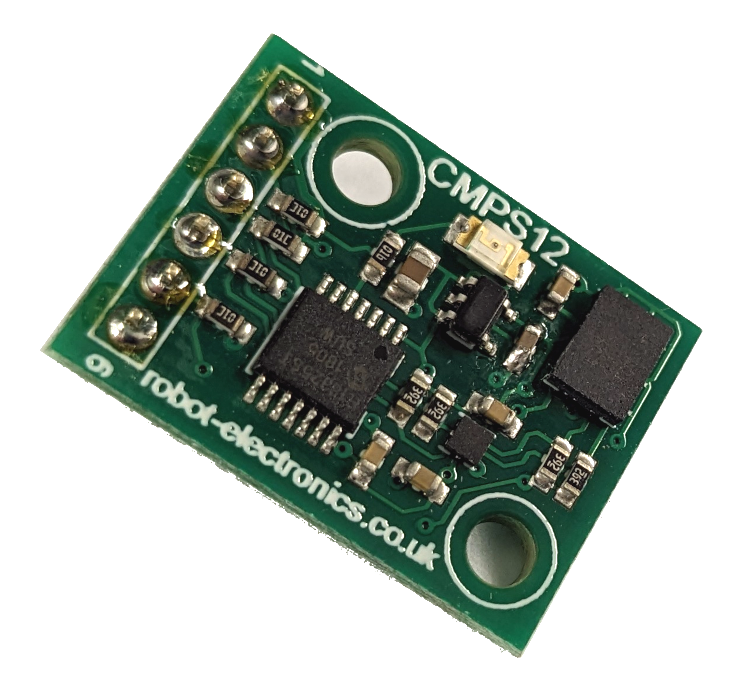
Electronic Compass, 7-Bit Address: 0x60
The electronic compass (Model CMPS12 from robot-electronics.co.uk) measures the orientation of the device relative to magnetic north and saves the measured angle, 0°-360°, in either a single byte, 0-255, or in two bytes in tenths of degrees, 0-3599, in addition to other features. In order to maintain sufficient accuracy of the measurement, the two byte representation must be used for this activity. It is not documented how often the compass updates it’s measurements; so we will assume it is the same rate as the CMPS03 model: every 33.3 ms. Therefore, if multiple values are downloaded from the compass during this update time, the received values will be unchanged and not necessarily representative of the current behavior of the system, namely for the second measurement. The important registers and address for the compass are provided in the table below.
Important
This compass is auto-calibrating upon power-up. When power is applied, the compass will always return a heading of 0 degrees until the device is rotated in 3D space for a few seconds; at which point it should return reasonably correct heading values.
Note that calibration happens upon power-up, not each time the code is run: as long as the 3.3V supply to the compass is not disabled (e.g., from disconnecting the computer or powering off the car if not connected), then the calibration will persist between debugging sessions.
Register # |
Read Function |
Write Function |
|---|---|---|
0 |
Software Version |
Command Register |
1 |
Heading as 0-255 |
N/A |
2 |
Heading, Tenths of Degrees, High Byte |
N/A |
3 |
Heading, Tenths of Degrees, Low Byte |
N/A |
4 |
Pitch angle, Degrees, Signed Byte |
N/A |
5 |
Roll angle, Degrees, Signed Byte |
N/A |
… |
… |
… |
Reading of the 0-3599 value from the compass is straight forward:
Ensure a minimum 2-element uint8_t array exists
use I2C_readData to fetch registers 2 and 3 at the same time
Combine the received bytes together to form the heading value
14.3.3. Ultrasonic Ranger, ADDR: 0x70
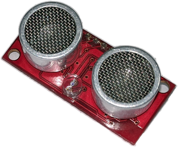
Ultrasonic Ranger, 7-Bit Address: 0x70
The ultrasonic ranger (Model SRF08 from robot-electronics.co.uk) measures the distance of objects from the device using (you guessed it!) ultrasound. When mounted on the car, the ranger may detect if the car is approaching a wall or another obstacle, etc., such that it may act accordingly. This is performed by the device emitting an ultrasonic pulse, which readily reflects off objects and returns back to the ranger as an “echo.” The object distance may be calculated by how long it took for the echo to return to the ranger. The ultrasonic pulse does not travel in a straight line, but instead radiates in cone-like fashion, where the cone width is approximately 60°. Therefore, care must be taken such that the ranger does not have obstructions in this cone (e.g., wires, the floor, etc.).
In order to acquire these measurements, the ranger must be asked to perform a measurement through writing to its control register. When this is done, the ranger emits an ultrasonic pulse and waits for the echo response(s). This process may take up to 80 ms to complete; therefore, once issuing the measurement request, the program should not interrogate the ranger until at least 80 ms have passed. Results from this measurement are stored in multiple registers, corresponding to the first echo, second echo, etc. Each echo’s distance (or time) is stored in a two byte form in units of either inches, centimeters, or microseconds, depending on the value written to the control register to start the measurement (0x50, 0x51, 0x52, respectively). In addition to the range measurement, the device also measures light intensity (also updated after writing to the control register). The value of this measurement is stored in a single byte where 0 indicates no light detected and 255 is the maximum light intensity detected. The registers and address for the ranger are provided in the table below.
Register # |
Read Function |
Write Function |
|---|---|---|
0 |
Software Revision |
Command Register |
1 |
Light Sensor |
Max Gain Register |
2 |
1st Echo High Byte |
Range Register |
3 |
1st Echo Low Byte |
N/A |
4 |
2nd Echo High Byte |
N/A |
… |
… |
… |
34 |
17th Echo High Byte |
N/A |
35 |
17th Echo Low Byte |
N/A |
As described above, measuring the distance to an object using the ranger is slightly more complicated than the operations required for the electronic compass. It is suggested to use the following structure to read the ultrasonic ranger:
<< This code only called once every 80 ms at most to prevent I2C bus lockup >>
Ensure a minimum 2-element uint8_t array exists
use I2C_readData() to fetch the registers storing the 1st Echo
Combine the received bytes together to form the distance value
Request a new measurement by writing 0x51 to the command register via I2C_writeData()
This code associated with this pseudocode must be called with a period greater than 80 ms. Reading the ranger faster than 80 ms will cause the ranger to return 0xFF for all registers. The first portion of this pseudocode reads the previously requested measurement from the ranger then the second portion requests a new measurement. Therefore, the first time this code is executed, the ranger will report an incorrect measurement as no measurement request has been made yet. This is acceptable behavior.
Note
The ranger measurement process takes up-to 80 ms to complete as the ranger must wait for an ultrasonic pulse to reflect (echo) off of an object and travel back to the device. Sound (ultrasound) travels at 343 m/s (~1 ms per 1 foot). The I2C bus may lock up if the ranger is interrogated too quickly after a measurement.
Ensure that the function used to interrogate the ranger is only called once per loop
14.3.4. RSLK I2C Wiring and Mounting
To reduce errors RSLK hardware wiring and attachment of I2C sensors, both the Electronic Compass and Ultrasonic Ranger have mount points added to the RSLK body. These mount points are identified in the image below. In addition to the mount points, an “I2C Bus Header” is also added: this is to provide the SDA and SCL connections to the compass and ranger.
Note
The RSLK has SCL incorrectly labelled as SDL on the bus header.

I2C sensor mount locations for RSLK.
Wiring of the I2C bus requires two pull-up resistors to be added, one each to the SDA and SCL lines; where all I2C devices share the same lines. The effective required circuit for connecting the compass and ranger to the MSPM0G3507 in then:

Activity schematic
With respect to the above schematic, the RSLK provides both the power and SDA/SDL interconnect to both the compass and ranger but does not provide the resistors or the connection to the microcontroller. Connection to the microcontroller is accomplished through the “I2C Bus Header” noted above. A fully wired RSLK with sensors should look similar to the image below. Not Shown: pull-up resistors and wire connection to GPIO pins.

Fully assembled I2C sensors on RSLK.
14.4. Instructions
14.4.1. Part A: Compass ONLY
This activity is difficult to debug as errors in both hardware and software may cause void I2C_readData() and void I2C_writeData() to lock up the program. Hopefully these issues are lessened with the new microcontroller in Fall 2025. Please see the debugging notes below for an incomplete list of possible issues.
Install only Electronic Compass on the RSLK. Do not add the Ranger yet. Wire the I2C bus such that SCL is provided by PA15 and SDA by PA16. Use resistors valued between 7 kΩ and 20 kΩ.
Note
Wiring for this activity should be done on the RSLK protoboard and left assembled. This helps to prevent numerous wiring errors that occur with the I2C lab; most commonly, having SDA and SCL swapped.
Download and import the course template project:
TemplateProject.zipand name it appropriately.Important
I2C support in the template project has been added for version 0.97 (2025-11-17). Ensure you’re using the correct one! If using an older version, any
I2C_functions or defines will cause compiler errors.Within a
GPIOInit()function: configure the GPIO pins PA15 and PA16 for the SCL and SDA alternate functions, respectively. Take note of the corresponding I2C module. Further: configure the pins to be Open-Drain (see Basic I/O).Important
It is possible that an RSLK may have the required pins blown. If this is the case, please give the car to an instructor or TA such that it can be removed from use for this activity.
Create a function
void I2CInit()which initializes the corresponding I2C module from the previous step to operate as an I2C Controller with a bit rate of 100 kbit/s and 7-bit addressing.Add calls to both
void GPIOInit()andvoid I2CInit()in the main function.Create a function
uint16_t readCompass()that follows the Compass pseudocode and returns the measured heading value as auint16_tvalue.Test the above function by calling it in the
main()functionwhile(1)loop with:printf("Compass: %4u\r\n",readCompass()); delay_cycles(3.2e6); // Wait 1/10 of a second
Note
The compass will return 0 if it is aligned with magnetic north. The RSLK mount of the compass on the car has the compass such that if the car is pointing towards magnetic north, the compass will instead be aligned with magnetic south and will return 1800.
Do not forget that the compass must be calibrated after power cycling. Rotate the car in 3D space for a few seconds to calibrate it. The calibration process is similar to calibrating the electronic compass within smartphones.
14.4.2. Part B: Add Ultrasonic Ranger
Once the compass portion of the activity is working, move on to developing the code for the ultrasonic ranger (leave compass installed):
Install the ranger onto the RSLK mount as shown in the photo above. Do NOT install it backwards!!.
Danger
The ranger require +5V power to operate; however, the MSPM0 is NOT 5V TOLERANT. Extreme care must be taken to prevent the 5V line from contacting the SDA or SCL lines, or any other pins on the Launchpad Board. The RSLK mount avoids requiring routing of the 5V power.
Create a function
uint16_t readRanger()that follows the Ranger pseudocode and returns the measured range value as auint16_tvalue. Be careful to ensure that this function is not called two with a period of less than 80 ms as it may lock up the I2C bus.Add ranger output to the print statement:
printf("Compass: %4u\tRanger: %4u\r\n",readCompass(),readRanger());
delay_cycles(3.2e6); // Wait 1/10 of a second
Note
It is normal for the first measurement of the ranger to be -1 (0xFFFF) when using the pseudocode provided to read the ranger. This is because the code is reading a “measurement” before one has been done. This can be ignored.
Turn the car on then test the code. As noted, the ranger requires 5V to operate and will not be powered unless the car is on. The LED on the backside of the ranger will blink once when powered on and then every time when a new measurement is requested.
Take a photo of the built circuit and a screenshot of the terminal output with both the compass and ranger working and submit to the corresponding Gradescope. You do not need to submit your code.
14.4.3. Debugging
Note
These debugging hints were for the previous iteration of the course hardware and may no longer be applicable (e.g., functions may not freeze as often or due to the same issues). Regardless, they are left here as they may still be useful in debugging the activity.
There are many causes for your program getting stuck within void I2C_readData() and void I2C_writeData(). Below is an incomplete list of possible causes to check:
Car is not on or car batteries are running low: The 5V power on the car must be on and fully powered for the compass and ranger to work. The 5V supply on the car can be checked via a multimeter. If the voltage is less than 5V, the batteries should be replaced. If the LED on the back of the ranger does not blink on power on, the batteries are likely low or the wiring is incorrect.
Make sure that all I2C calls are using the correct I2C module.
The compass and ranger will lock up the I2C bus in some cases if a transaction fails. It is suggested to power cycle the car (turn off and back on) each time the code is run to ensure this isn’t the case. Once the code with the compass and ranger begins printing consistently, this power cycling can stop as it is ensured that the bus isn’t failing.
A common cause for the I2C to lock up is that the ranger is interrogated too quickly after a measurement is requested. Ensure that repeated requests to the ranger are at least 80 ms apart.
It is very easy to switch the SCL and SDA. Ensure these connections are correct, along with the rest of the hardware.
Make sure to call
I2CInit()andGPIOInit()!