10. Motors: PWM and Encoders
Important
This activity may be completed in groups of 2 students as an RSLK is required.
10.1. Purpose
This activity introduces the implementation and use of Pulse Width Modulation to control wheel speed and Encoders to measure wheel speed and drive distance.
10.2. Hardware and Tools
TI-RSLK Robotic Car
10.3. Description
This activity consists of two independent parts: PWM implementation and Encoder support. These functionality will be combined for Laboratory 3.
10.4. Part 1: PWM
10.4.1. Description
This portion of the activity will serve as a guide to implement Pulse Width Modulation, or PWM, in order to control the RSLK drive wheels’ speeds. The motors on the car are connected through an H-bridge chip (DRV8838) such that no hardware needs to be built for this application. The connections on the RSLK are as shown in the figure below.

Wiring of motors on RSLK
The pins for Enable and Direction were of course initialized for use in Laboratory 1; where fixed speed control was built into the template project. The speed control for this activity and future laboratories must be implemented using two PWM outputs generated from a Timer_A module, one for each wheel. While the DRV8838 and motors will work using a huge range of frequencies, for the purposes of this class a PWM period of 24 kHz should be used.
10.4.2. PWM Generation
Implementation of PWM is fairly straight forward as long as it is clear how to configure and use a timer in order to track time. PWM is generated by using a timer’s count to trigger an output to change value when a specific count value is reached. This additional functionality is supported by a Timer_A module’s Capture Compare Register, or CCRn; configured to operating in Compare Mode. A CCRn is capable of directly driving a linked GPIO pin, as opposed to requiring code to explicitly change the pin value, as described in the figure below. In the below figure, the Timer_A module is configured to operate in Up Mode, where the value for Nperiod, or CCR0 (Capture Compare Register 0), is specified by the Up Mode configuration’s .timerPeriod field.
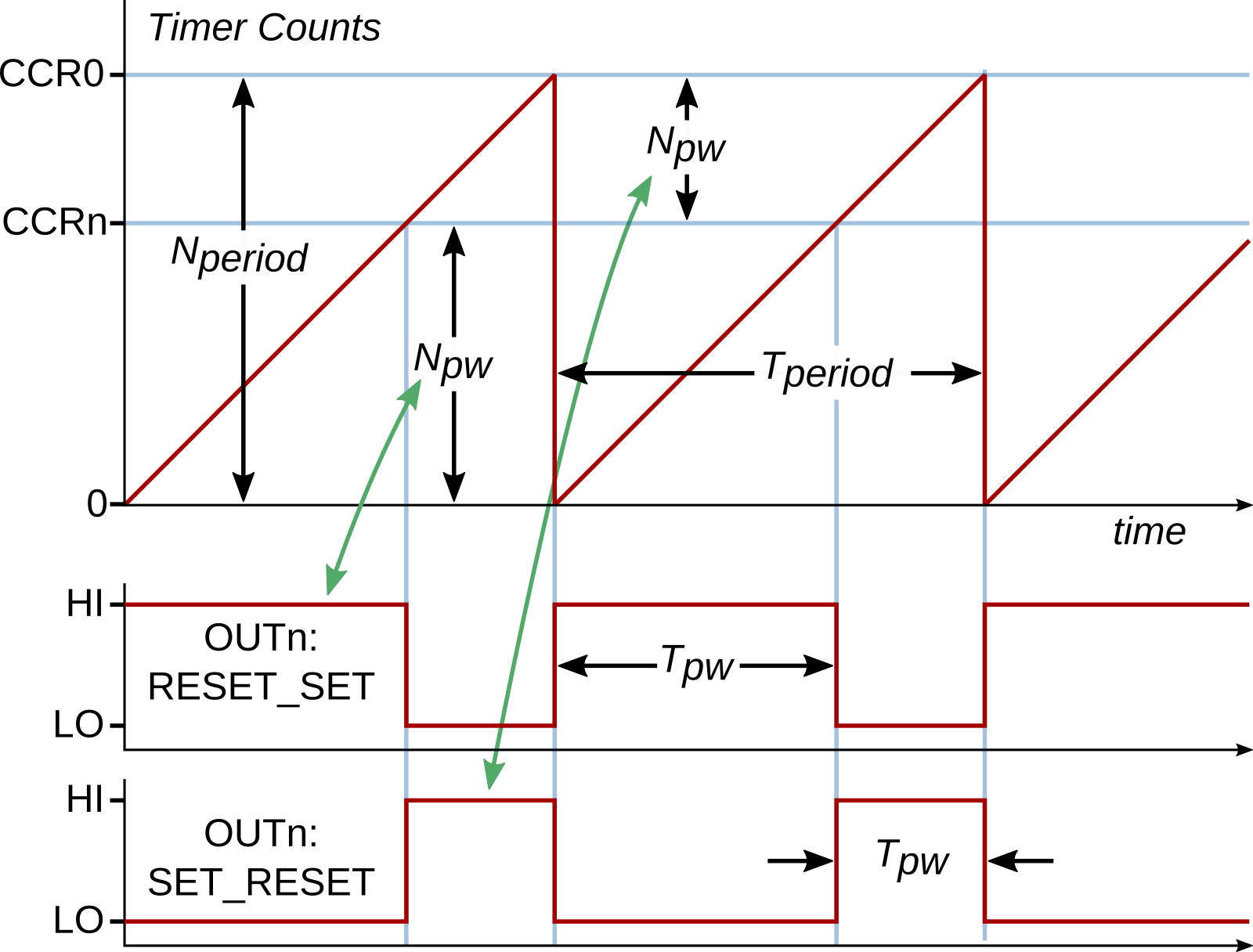
Timer_A OUTn PWM behavior
As shown, CCR0 is used to control the timer period (true for Up Mode and Up-Down Mode) and does not need to be explicitly configured to do so. A second CCRn is then configured in the Compare Mode (using the struct type Timer_A_CompareModeConfig) to generate the PWM output, denoted as the OUTn signal. The figure shows two different variations on the generated PWM: RESET_SET and SET_RESET, where one is the inverse of the other. These would be selected with the .compareOutputMode field values of either TIMER_A_OUTPUTMODE_RESET_SET or TIMER_A_OUTPUTMODE_SET_RESET, respectively (among other modes).
Once configured appropriately, the PWM would be generated without intervenion; that is, the PWM signal will be continuously generated until the program instructs it to be changed or stopped. This implies that no timer interrupts are necessary to maintain said operation. To change the PWM duty cycle, a new value for the CCRn compare value must be computed and assigned to the CCRn via the function Timer_A_setCompareValue().
10.4.3. PWM Output Routing
As noted, the CCRn module will control an output signal OUTn. By default, this OUTn signal is not passed to a GPIO pin. This is changed by configuring the applicable GPIO pin into an Alternate Function mode (GPIO Alternate Functions). It should be noted that each GPIO pin is capable of being linked to only a few signals; therefore, it is necessary that the correct GPIO pin is selected to support the generated output signal. Conversely, if PWM must be generated on a specific pin, as is the case with the RSLK, then the appropriate Timer_A module and CCRn must be configured to generate the PWM.
The OUTn signals associated with each Timer_A module and CCRn are denoted as TAm.n in GPIO Alternate Functions; where m in TAm.n indicates the timer module and n indicates the CCRn number. For example, P5.6 is noted to support the alternate function TA2.1 within the GPIO Alternate Functions table; indicating P5.6 associates with CCR1 of Timer_A Module 2 (TIMER_A2_BASE). Of course, as the PWM is an Output, the GPIO alternate function must be set as an output as well.
10.4.4. Instructions
The following instructions will guide you towards configuring the RSLK to control both motor speeds.
Ensure the RSLK is on a foam block before powering on. This will prevent cars from driving off the benches and becoming damaged.
Import a new
Template Projectand name it appropriately.Determine the required GPIO pins to output the PWM signal on (see motor schematic above). From this information, determine the Timer_A instance to use and the Capture Compare Register (CCRn) modules needed to generate the PWM on the appropriate pins. See here: GPIO Alternate Functions. Note that the syntax TAm.n is used in the alternate functions table to denote CCRn of Timer_A instance m.
Within a
GPIO_Init()function, configure the necessary outputs:The Direction and Enable lines for each motor must be configured as normal outputs. Set these outputs to both enable the motors and set the direction to forward.
See also
Refer back to Lab 1 or the
TI-RSLK Pin Mapfor the motor pinouts. Remember that the wheels will rotate forwards if the Direction line is low.The PWM outputs must use the necessary alternate function configurations as described here: GPIO Alternate Functions
Within a
Timer_Init()function, initialize the required Timer_A instance such that it resets at the desired PWM frequency (24 kHz) using a clock divider of 1. Up Mode should be used for this class. No reset interrupt is need.Note
The period require for this timer 1/(24 kHz) is much smaller than the previously used 0.1 s. As such, it would make sense to use a much smaller divider (e.g., /1) for the timer input clock in order to allow for higher resolution PWM; that is, have more timer counts in one reset period, allowing for more flexibility and finer control of changes in setting of the PWM duty cycle.
Also within
Timer_Init(): configure the applicable CCRn modules: Create the initialization struct (typeTimer_A_CompareModeConfig), populate the fields, and apply the configuration:.compareRegister: Select the appropriate CCRn to generate the PWM. Only one CCRn may be initialized at a time; therefore, the formTIMER_A_CAPTURECOMPARE_REGISTER_1 | TIMER_A_CAPTURECOMPARE_REGISTER_2cannot be used here..compareInterruptEnable: No compare interrupt is needed for PWM..compareOutputMode: Set the output mode to match the RESET_SET functionality. While the SET_RESET mode would work, the instructions below assume RESET_SET..compareValue: Set an initial compare value that corresponds with 0 % duty cycle PWM.Apply the CCRn configuration with the function
Timer_A_initCompare().Repeat steps 1-5 for additional CCRns to be configured.
Start the timer within
Timer_Init()after all configurations have been applied.Add
GPIO_Init()andTimer_Init()to themain()function at the appropriate place.Within the
main()functionwhile(1)loop: add code that will read a key from the terminal (usinggetchar()) and implement the following pseudocode:Read terminal input If key pressed is 'a': Add 100 to the left wheel CCRn compare value Limit the compare value to no greater than 90 % of the timer period Apply the new compare value If key pressed is 'z': Subtract 100 from the left wheel CCRn compare value Ensure the compare value does not go negative <- Implies that variable needs to be signed! Apply the new compare value Repeat the above for right wheel and keys 's' and 'x'
Test the code. If operating correctly, the user should be able to cause the left and right wheels to accelerate/decelerate independently of the other.
Important
Remember that the car needs charged batteries and must be on for the motors to run. The USB cable only powers the MSP432 and the components directly connected to it (e.g., the LEDs). The Blue LED near the power button must be lit brightly. The car batteries must be replaced/added if the LED does not light, or is lit dimly, when the power button is pressed.
If desired, the car may be set to a speed, unplugged from the computer, and placed on the floor. It will likely be seen that the car does not travel in a straight line but instead turns with a gradual arc.
Save the code to be submitted to the Gradescope assignment.
10.5. Part 2: Encoders
10.5.1. Description
PWM speed control of the motors on the RSLK works well but the control is not accurate with respect to absolute speed. This causes there to be a slight speed difference between the left and right motors on the car as they are independent drives; causing the cars to turn or drive along an arc when motors are receiving equivalent pulse widths. Therefore, it is useful to have a measure of the actual speed of the motors in order to adjust the PWM as necessary to achieve the desired speed. This functionality will not be accomplished in this activity but will instead be completed in Laboratory 3.
This activity guides through implementing a timer to Capture the motor speed and distanced traveled; which is indicated by an attached magnetic encoder. A Hall effect sensor produces a digital signal corresponding to the rotation of the magnetic encoder. The RSLK has two Hall effect sensors per encoder/wheel, providing two digital outputs per side:
The two sensor locations are noted as the green and yellow marks as shown in the animation above. The outputs of said sensors are provided in the plot on the right as the wheel rotates. The rotating red/blue disk is the magnetic encoder rotating with the DC motor. It is clear that the encoder is rotating much faster than the wheel: the motor/encoder are connected to the wheel through an effective 360:1 gear train. For purposes of demonstration, the video above shows a gear train of 10:1.
Only one hall effect sensor is required to measure the wheel speed; two are included to support detection of spin direction. Measurement of direction is not required in this activity.
Measurement of speed can be accomplished by tracking the timing between the rising and/or falling edges of the sensor output. This, of course, can be supported by a Timer_A instance; this time using the Capture Mode.
10.5.2. Timer_A Capture Description
The Timer_A Capture functionality behaves akin to the Compare Mode (used to generate PWM) but in reverse: instead of producing external events when the timer reaches a certain value, the Capture mode uses an external event to cause the CCRn to save the current timer value. The external signal producing said events is named the CCInA for Capture Compare Input n Line A. This functionality is described in the figure below.
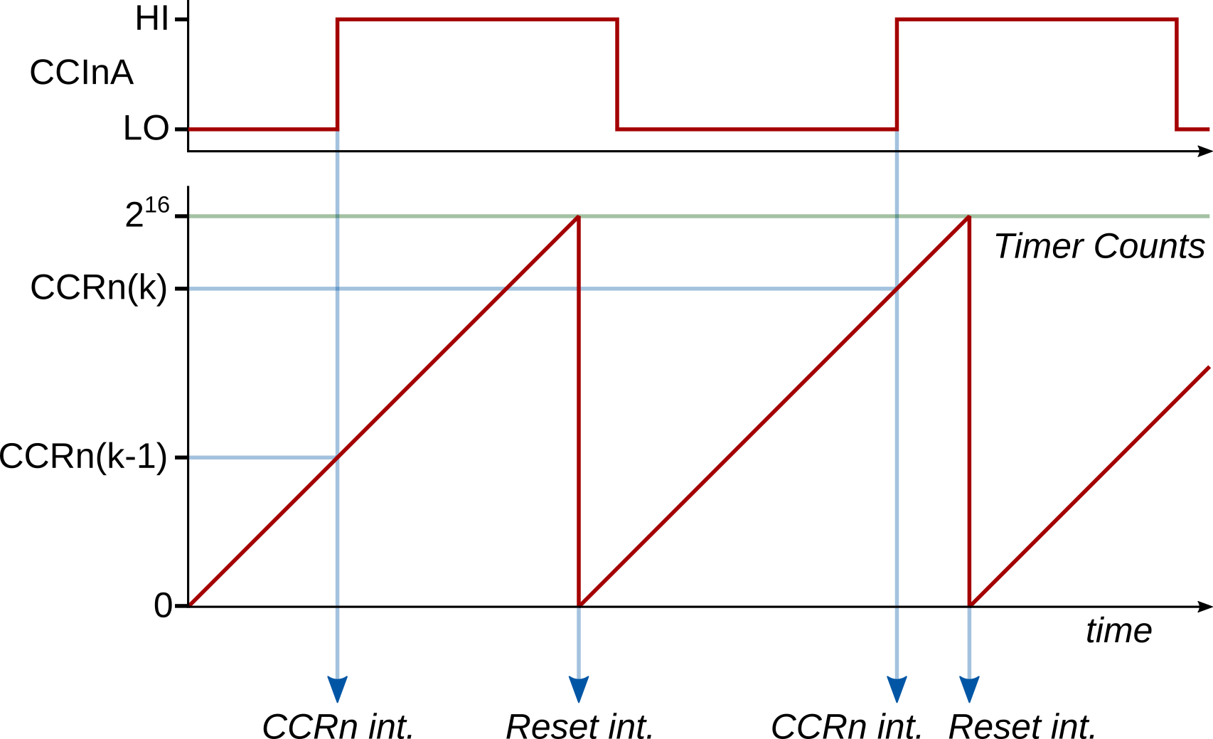
Timer_A capture operation in continuous mode, triggering on rising edge of CCInA.
We will use Timer_A in continuous mode when using the encoders. This provides for the largest sample period range, allowing for fewer timer resets during each measurement (more efficient). Continuous mode operates exactly the same as Up Mode; however, the timer only resets due to integer overflow after counting past its maximum value of 65535. This frees CCR0 to be use used in capture mode as opposed to it being used to control the timer period.
When an external event occurs on CCInA, triggering a timer compare, the current count value is stored within the CCRn attached to the external signal. Both rising and falling edges may be used to trigger the compare event. These events may be directly used to calculate distance traveled for a wheel: each event indicates a rotation of 1/360 of the wheel circumference since the last event (rising-to-rising or falling-to-falling); therefore, counting the events effectively serves as a distance measurement. Likewise, the speed of the rotation may be calculated through the time difference between the events.
Measuring the time difference between two capture events that happen within the same timer period is straight forward: subtract the difference between the captured timer counts and calculate the time knowing the timer clock:
where \(N_\mathrm{cap}(k)\) is the timer capture value for sample \(k\), and \(f_\mathrm{TCLK}\) is the timer clock.
This becomes slightly more difficult when the events span across timer reset periods. For example, if the timer overflows once between capture events, then the calculation becomes:
where \(65536-N_\mathrm{cap}(k-1)\) is the number of counts between the previous capture event and the overflow event.
This math can be extended to multiple overflows between capture events by simply adding \(65536\) for each overflow that has occurred, leading to:
where \(N_\mathrm{overflows}(k)\) is the number of overflows that have occurred between two capture events.
10.5.3. Timer_A Capture Implementation
As noted above, the Timer_A instance should be set up to operate in Continuous Mode. Again, this mode is effectively the same as Up Mode except that the timer will always count to 65535 prior to overflow instead of to the value stored within CCR0. This requires using the initialization struct Timer_A_ContinuousModeConfig instead of Timer_A_UpModeConfig. Note that these structs only differ in that the continuous mode version does not have a .timerPeriod field. To match this change, when starting the timer using startCounter(), the timerMode argument must be TIMER_A_CONTINUOUS_MODE.
With the Timer_A instance configured for continuous mode, the CCRns may be configured to support Capture Mode. This is done by creating a Timer_A_CaptureModeConfig struct and populating the fields appropriately. Make sure to read the description for each field as provided in the linked documentation: some fields should always take the same value. Some additional notes:
A capture event must be acted upon in a timely manner. Therefore, it is necessary to enable the associated interrupt for each CCRn used in capture mode.
Likewise, the number of timer resets/overflows must be tracked as well. This requires that the overflow (TAIE) interrupt be enabled as well.
It does not matter which encoder edge is selected to trigger the capture event; however, both edges should not be used together (at least for this course).
Within the Timer_A interrupt(s), several things must be tracked:
The number of timer overflows since the last compare event: this is necessary to support calculation of the time between successive compare events,
The timer value of the last compare event: this is also required to calculate the time between successive compare events,
The total number of compare events: to track total rotation or distance.
Using these quantities, the time difference between successive compare events may be calculated from this equation.
Note
As you will see by the instructions below, these three points are incorperated, but the actual implementation does not use independent variables for the first two points; it is condensed into one counter variable.
10.5.4. Instructions
The following instructions will guide you towards configuring the RSLK to be used as a crude “tape measure”, where the RSLK is manually pushed over a distance to measure. Only one of the RSLK motor encoders will be used.
Import a new
Template Projectand name it appropriately.Create a
GPIOInit()function and initialize one of the pins P10.4 (right wheel encoder) or P10.5 (left wheel encoder) to the appropriate Alternative Function. Take note of the required Timer_A instance number and CCRn register required for the pin selected. The pin must be configured as an Input. Note that the syntax TAm.CCInA is used in the alternate functions table to denote the CCRn input of Timer_A instance m.Create a
TimerInit()function and initialize the required Timer_A instance to continuous mode:The timer should be using a divider of 1.
The interrupt must be enabled.
Still within
TimerInit(): configure the required CCRn for capture mode using the struct typeTimer_A_CaptureModeConfig.The output mode field (
.captureOutputMode) is not used and may be omitted. All other fields must still be specified.The interrupt must be enabled.
Register both interrupts (
TIMER_A_CCRX_AND_OVERFLOW_INTERRUPTandTIMER_A_CCR0_INTERRUPT) to trigger anEncoder_ISR()function.Note
Remember that each Timer_A module has two interrupts. One is triggered by a reset or overflow and a capture/compare event from CCR1-CCR4. The other is only triggered by CCR0. If using CCR1-CCR4 only one
Timer_A_registerInterrupt()call is required. Two calls are required if using CCR0. While the two interrupts are inherently different, they can be configured to trigger the same function.Finally, start the timer towards the end of
TimerInit().Create four global variables, one each to:
uint32_t enc_totalKeep track of total encoder events, useful in measuring distance traveled.int32_t enc_counts_trackKeep track the timer counts since the capture event (must be signed!).int32_t enc_countsFinal value of timer counts between capture events.uint8_t enc_flagA flag to denote that a capture event has occurred.
Create the
Encoder_ISR()function. Within this function, implement the following pseudocodeCheck to see if timer reset interrupt has occurred. If yes: Clear the reset interrupt flag Add 65536 to enc_counts_track Check to see if a capture event ocurred. If yes: Clear the capture event interrupt flag Increment enc_total (total number of capture events that have occurred) Calculate enc_counts as enc_counts_track + capture value Set enc_counts_track to -(capture value) Set enc_flag to 1
Note
Comments on the pseudocode above:
Use
Timer_A_getEnabledInterruptStatus()to check the overflow/reset status.Use
Timer_A_getCaptureCompareEnabledInterruptStatus()to check the CCR status.The math for
enc_counts/enc_counts_trackis taken directly from this equation, excluding the frequency division. The equation is built piece-by-piece:enc_counts_trackis set equal to \(-N_\mathrm{cap}(k-1)\) (second to last line of pseudocode).Each overflow is added into
enc_counts_trackone-by-one (\(65536 N_\mathrm{overflows}(k)\))The most recent count value, \(N_\mathrm{cap}(k)\), is combined with
enc_counts_trackto produceenc_counts.
Refer to Timer Interrupt Handling for the functions to check and set the interrupt flags.
The capture value may be obtained using the function
uint16_t Timer_A_getCaptureCompareCount( uint32_t timer , uint16_t compareRegister )
Within the
main()functionwhile(1), add the segment of code:if(enc_flag){ // Check to see if capture occurred enc_flag = 0; // reset capture flag uint16_t distance = ... ; // Calculate distance travelled in mm uint16_t speed_rpm = ... ; // Calculate the instantaneous wheel speed in rpm uint16_t speed_mm = ... ; // Calculate the instantaneous car speed in mm/s printf("%5u mm\t%5u rpm\t%5u mm/s\r\n",distance,speed_rpm,speed_mm); }
Finish the calculation for the
distancevariable. Each compare event corresponds to 1/360 of a wheel rotation. You must measure the wheel diameter or circumference.\[c = 2 \pi r\]Finish the calculation for the
speed_rpmvariable. This is an instantaneous value that should be calculated from just theenc_countsvariable, knowing there are 1/360 compare events for each full rotation. rpm is revolutions per minute.\[\omega\left[\mathrm{rpm}\right]= \frac{1}{360}\frac{1}{\Delta t}\frac{60~\mathrm{s}}{1~\mathrm{min}}\]Hint
The value for \(\Delta t\) in the above equation should be calculated from
enc_counts(the numerator). All of the math in the numerator for calculating \(\Delta t\) (Equation) was done in the interrupt.Finish the calculation for the
speed_mmvariable. This is an instantaneous value in mm/s that should be calculated from theenc_countsvariable and the wheel dimensions.\[v = \omega\left[\mathrm{rad/s}\right] r = \frac{2 \pi}{360}\frac{1}{\Delta t} r\]Test the code by pushing the car GENTLY across the table surface. Be careful to not touch the encoders while pushing the car as it may break the gear train or cause the clutch to slip. Verify the terminal output of distance by measuring the distance traveled.
Take a screenshot of the terminal output after the RSLK has been pushed some distance. Submit this screenshot and the final code to the corresponding Gradescope assignment along with the final code from Part 1.