LP-MSPM0G3507 Launchpad Modifications
The MSPM0G3507 launchpad board (LP-MSPM0G3507) used as the RPI-RSLK controller requires several modifications prior to being installed into the RPI-RSLK. These modifications are only necessary for if the board is installed on the RPI-RSLK; if not using the board as part of the RSLK, these changes are optional; though marked changes 1-3 are recommended.
See the figure below for the location of the marked changes.
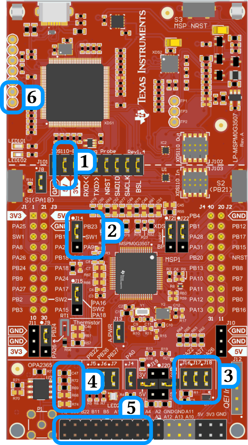
Marked location for LP-MSPM0G3507 changes. Unmodified image source from LP-MSPM0G3507 datasheet, TI document number SLAU873D.
- Numbered Changes:
Remove 5V jumper connecting debugger side to microcontroller size. We don’t want 5V available (to reduce chance that we blow a pin). Not installed in RPI-RSLK: Can leave connected if careful with the 5V pins.
Switch J14 jumper such that it connects PA9 to the pin labeled ‘SW1’ instead of PB23 (default). Not installed in RPI-RSLK: Can leave as-is but be aware that SW1 will be connected to PB23 and PA9 is unavailable.
Remove jumpers J16,J17,J18. This disables the light sensor subcircuit and allows PA22, PA26, and PA27 to be used for other purposes. Not installed in RPI-RSLK: Can leave as-is but be aware that PA26 will be directly connected to ground and PA22,PA27 may not function as expected as they are still part of the light sensor subcircuit.
Remove R72 and add a 0ohm resistor (or solder bridge) to R74. This allows PB25 to be used with BMP6. Not installed in RPI-RSLK: Don’t make change, not needed (PB25 not routed to populated headers).
Install 2x8 pin socket on the bottom header, covering from A0/B27 to A6/A7. The pin socket needs to be pointing down (oriented same as for J1-J4 sockets).
Install 1x2 pin socket on the debug header as indicated, pins corresponding to +3.3V and GND (unlabeled). Orientation should down, same as in previous.