|
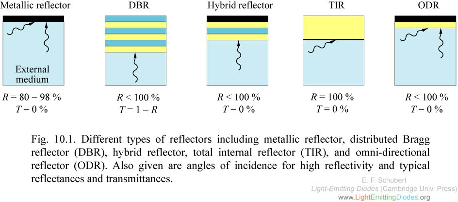
Fig. 10.1. Different types of reflectors including metallic reflector, distributed Bragg reflector (DBR), hybrid reflector, total internal reflector (TIR), and omni-directional reflector (ODR). Also given are angles of incidence for high reflectivity and typical reflectances and transmittances.
|
|
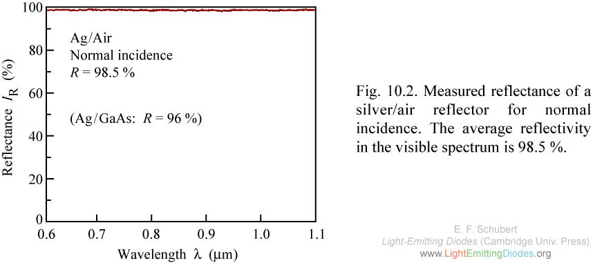
Fig. 10.2. Measured reflectance of a silver/air reflector for normal incidence. The average reflectivity in the visible spectrum is 98.5 %.
|
|
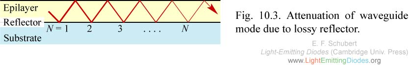
Fig. 10.3. Attenuation of waveguide mode due to lossy reflector.
|
|
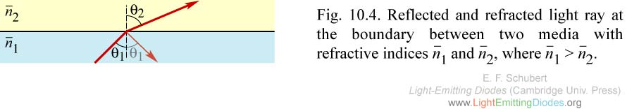
Fig. 10.4. Reflected and refracted light ray at the boundary between two media with refractive indices n1 and n2, where n1 > n2.
|
|
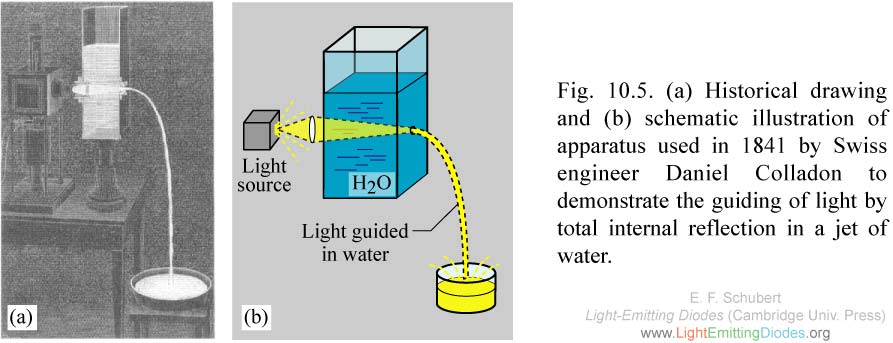
Fig. 10.5. (a) Historical drawing and (b) schematic illustration of apparatus used in 1841 by Swiss engineer Daniel Colladon to demonstrate the guiding of light by total internal reflection in a jet of water.
|
|
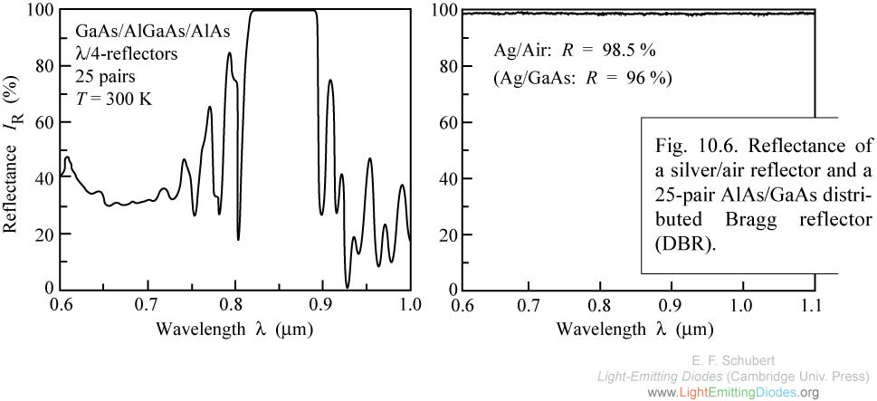
Fig. 10.6. Reflectance of a silver/air reflector and a 25-pair AlAs/GaAs distri- buted Bragg reflector (DBR).
|
|
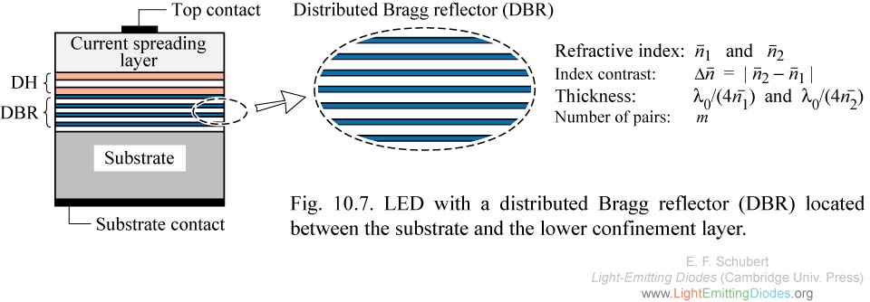
Fig. 10.7. LED with a distributed Bragg reflector (DBR) located between the substrate and the lower confinement layer.
|
|
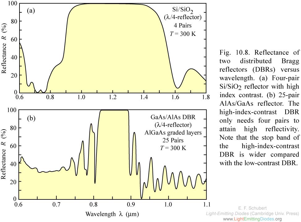
Fig. 10.8. Reflectance of two distributed Bragg reflectors (DBRs) versus wavelength. (a) Four-pair Si/SiO2 reflector with high index contrast. (b) 25-pair AlAs/GaAs reflector. The high-index-contrast DBR only needs four pairs to attain high reflectivity.
|
|
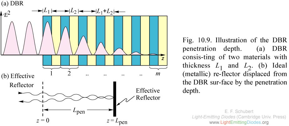
Fig. 10.9. Illustration of the DBR penetration depth. (a) DBR consis-ting of two materials with thickness L1 and L2. (b) Ideal (metallic) re-flector displaced from the DBR sur-face by the penetration depth.
|
|
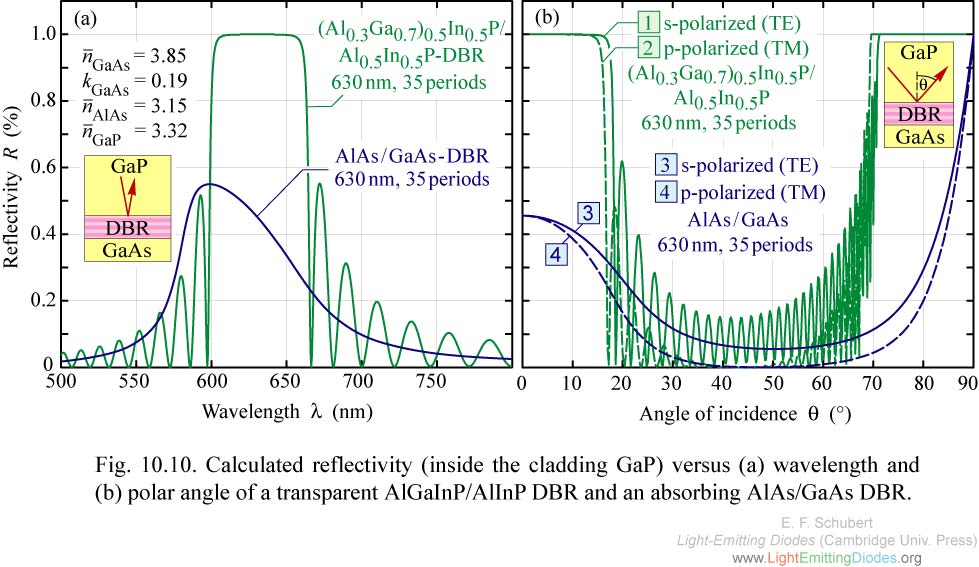
Fig. 10.10. Calculated reflectivity (inside the cladding GaP) versus (a) wavelength and (b) polar angle of a transparent AlGaInP/AlInP DBR and an absorbing AlAs/GaAs DBR.
|
|
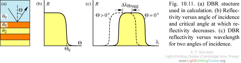
Fig. 10.11. (a) DBR stucture used in calculation. (b) Reflectivity versus angle of incidence and critical angle at which reflectivity decreases. (c) DBR reflectivity versus wavelength for two angles of incidence.
|
|
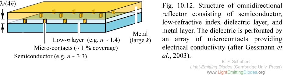
Fig. 10.12. Structure of omnidirectional reflector consisting of semiconductor, low-refractive index dielectric layer, and metal layer. The dielectric is perforated by an array of microcontacts providing electrical conductivity (after Gessmann et al., 2003).
|
|
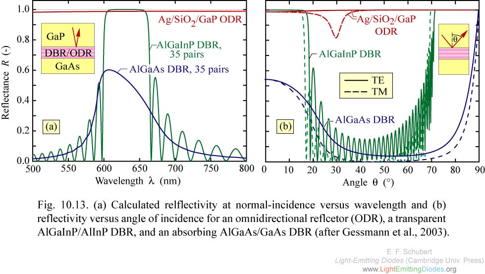
Fig. 10.13. (a) Calculated relflectivity at normal-incidence versus wavelength and (b) reflectivity versus angle of incidence for an omnidirectional reflcetor (ODR), a transparent AlGaInP/AlInP DBR, and an absorbing AlGaAs/GaAs DBR (after Gessmann et al., 2003).
|
|
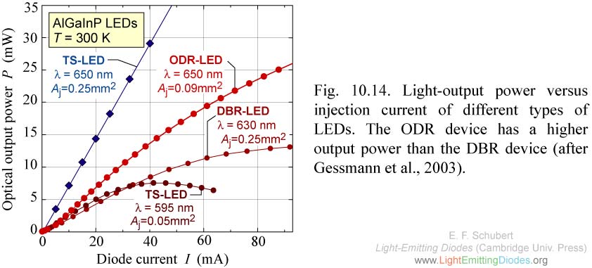
Fig. 10.14. Light-output power versus injection current of different types of LEDs. The ODR device has a higher output power than the DBR device (after Gessmann et al., 2003).
|
|
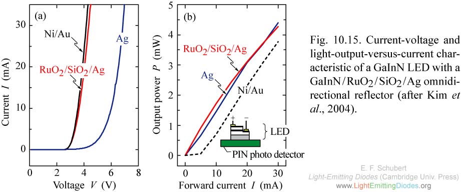
Fig. 10.15. Current-voltage and light-output-versus-current characteristic of a GaInN LED with a GaInN/RuO2/SiO2/Ag omnidirectional reflector (after Kim et al., 2004).
|
|
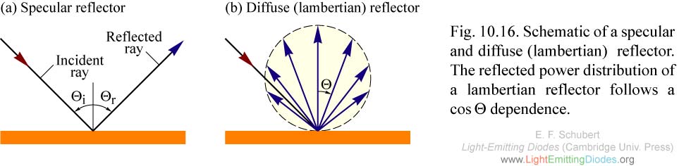
Fig. 10.16. Schematic of a specular and diffuse (lambertian) reflector. The reflected power distribution of a lambertian reflector follows a cos theta dependence.
|
|
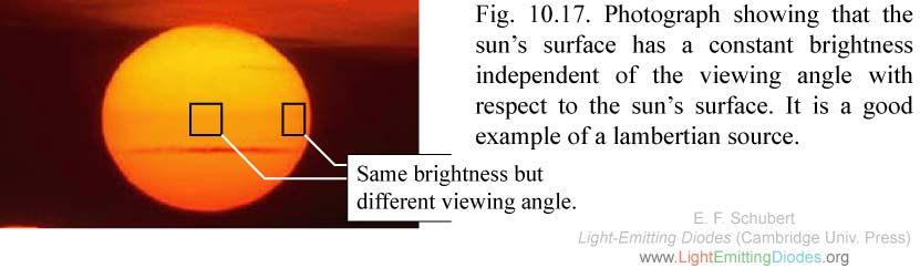
Fig. 10.17. Photograph showing that the sun’s surface has a constant brightness independent of the viewing angle with respect to the sun’s surface. It is a good example of a lambertian source.
|
|
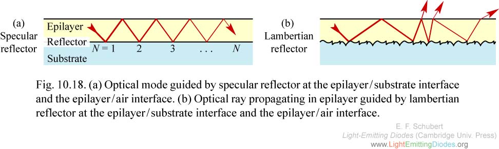
Fig. 10.18. (a) Optical mode guided by specular reflector at the epilayer/substrate interface and the epilayer/air interface. (b) Optical ray propagating in epilayer guided by lambertian reflector at the epilayer/substrate interface and the epilayer/air interface.
|
|
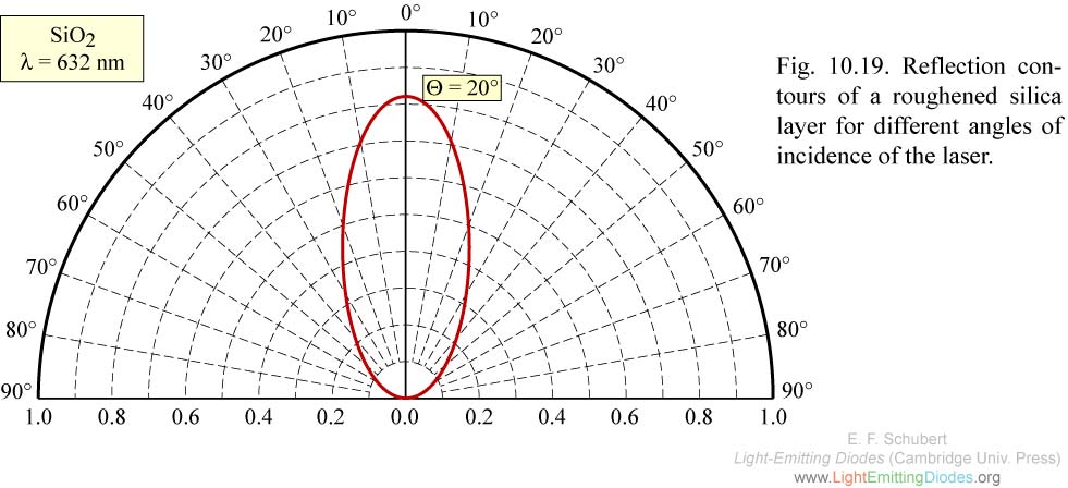
Fig. 10.19. Reflection contours of a roughened silica layer for different angles of incidence of the laser.
|