LCD02 - I2C/Serial LCD
Technical Documentation
Overview
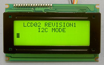
The I2C and serial display driver provides easy operation of a standard
20*4 LCD
Text display. It requires only a 5v power supply and the two data
connections for either mode, freeing up pins on your processor. Many
useful text formatting
functions are provided (described below) and also the ability to put
together
custom characters into memory which can be called off as required.
There is a 64 byte FIFO buffer to ensure a minimum of delay in writing
to the
display.
Connections
Pins 1 and 9 are unconnected - only pins 2 - 8 are used.
Serial/I2C Mode selection
A single jumper link is used to select Serial or I2C mode. When the jumper is
present (factory default) the module is in serial mode. When the jumper is
removed the module is in I2C mode. The mode jumper is only checked as part of
the power-up sequence, so make sure the display is off before changing modes. If
you change the link position while the module is powered, nothing will change
until next time you switch on.
FIFO
Because the I2C communications operate faster than the
display can accept data, all commands and text you send to the display are
placed in the FIFO (First In, First Out) buffer. This data is sent to the
display as fast as it will accept it. The FIFO is 64 bytes in length and the number of
free bytes can be returned in either mode. When sending lots of text to the
display, you should check the number of free bytes so you don't overflow the
buffer. If the buffer does overflow, the excess bytes are ignored. The FIFO
buffer exists in Serial mode too, but at 9600 the display is fast enough and you
are unlikely to need to check it.
I2C Operation
I2C Bus
The I2C display is located on the I2C bus at an address of 0XC6. The
SCL and SDA lines should have pull-up resistors on them somewhere on the bus.
You only require 1 pair of resistors for the whole I2C bus, not specifically for
the LCD02. They are normally on the master controller and you may already have
them. If not, anything between 1k8 and 10k should work. I recommend 1k8 for best
noise immunity.
Display control commands
The LCD02 has four registers, three of which are read only information
registers. Register 0 is a dual purpose register, when written, it is the command register where all of the instructions from
the commands section should be sent. When read it returns the number of free bytes in the FIFO
buffer.
| register |
Read |
Write |
| 0 | Number of free bytes in FIFO buffer | Command register |
| 1 | Keypad state Low byte | x |
| 2 | Keypad state High byte | x |
| 3 | Version | x |
Serial operation
The Serial mode operates over a link with a baud rate of 9600 bps (no parity, 2 stop bits) and 5v signals, Do NOT connect RS232 directly to the module - you will destroy it. Use a MAX232 or equivalent to convert the RS232 levels to 5v. Operation is with the same command set as the I2C mode with an additional set of commands to request data to be sent i.e. the software version.
Commands (for both I2C and Serial)
| decimal |
command |
description |
| 0 | null (ignored) | Ignored as a no operation |
| 1 | Cursor Home | Sets the cursor to the home position (top left) |
| 2 | Set cursor (1-80) | Cursor to a position specified by the next byte, where 1 is the top left and 80 is the bottom right |
| 3 | set cursor (line, column) | Sets cursor using two bytes, where first byte is the line and the second byte is the column |
| 4 | Hide cursor | stops the position cursor from appearing on the display |
| 5 | Show underline cursor | Changes the cursor to the underline type |
| 6 | Show blinking cursor | Changes the cursor to the blinking type |
| 8 | Backspace | deletes the preceding character from the current position on the display |
| 9 | Horizontal tab (by tab set) | Moves the current position across by the tab space set by command 18 (default tab space 4) |
| 10 | Smart line feed | Moves the cursor down one line to the position beneath in the same column |
| 11 | Vertical tab | Moves the cursor up one line to the position above in the same column |
| 12 | Clear screen | Clears the screen and sets cursor to the home position |
| 13 | Carriage Return | Moves the cursor to the start of the next line |
| 17 | Clear Column | Clears the contents of the current column and moves cursor right by one column |
| 18 | Tab set | Sets the required tab size, the following byte can be a size of between 1 and 10 |
| 27 | Custom char generator | allows 8 custom chars to be built. See custom char generator below |
| 32-255 | ASCII chars | Writes ASCII chars straight to the display |
Additional commands (Serial only)
| decimal |
command |
description |
| 14 | FIFO status | Results in the module returning its FIFO status, the number of free bytes from 0 to 64 |
| 15 | Software version | Results in the module returning its single byte software version |
| 16 | Keypad status | Returns keypad input status, two bytes returned with the low byte first (see keypad section) |
Custom char generator
Custom characters can be generated by sending an 8 byte map. The first thing
that must be done is to send a command of 27 to indicate that you intend to make
a custom char. Next you have to specify the position in ram of one of the 8
available chars you intend to build, the 8
chars are mapped at positions 128-135. Then the pattern should be sent as below.
How to calculate an 8 byte character pattern:
Eight bytes are sent with the highest bit masked on, the next two bits are
ignored (x) and the final 5 bits show the line pattern.
| Bit 4 | Bit 3 | Bit 2 | Bit 1 | Bit 0 | sent byte | ||
|---|---|---|---|---|---|---|---|
| Byte 0 | 1xx00000 (128) | ||||||
| Byte 1 | 1xx00100 (132) | ||||||
| Byte 2 | 1xx01110 (142) | ||||||
| Byte 3 | 1xx10101 (149) | ||||||
| Byte 4 | 1xx00100 (132) | ||||||
| Byte 5 | 1xx00100 (132) | ||||||
| Byte 6 | 1xx00100 (132) | ||||||
| Byte 7 | 1xx00000 (128) |
So to build the above arrow into location 128 you would send this sequence to the command register:
Now the char is built into a memory location it can be called at any time as long as the module remains powered by simply sending the address between 128 and 135.
Keypad input
An added feature of the module is the ability to connect a 3*4 Keypad, the module will automatically scan the status of the keys at regular intervals. The result is then provided in two bytes for easy use, shown by the diagram below. Each bit represents the row and column of each button on the keypad. The second row is the keypad characters when using our keypad.
| High | byte | Low | byte | |||||||||||||
|
0 |
0 | 0 | 0 | 4/3 | 4/2 | 4/1 | 3/3 | 3/2 | 3/1 | 2/3 | 2/2 | 2/1 | 1/3 | 1/2 | 1/1 | |
|
0 |
0 | 0 | 0 | # | 0 | * | 9 | 8 | 7 | 6 | 5 | 4 | 3 | 2 | 1 |
Any key press will result in the corresponding bit in the byte being driven
high. In I2C mode these bytes are available for reading from registers one and
two.
In serial mode, just send 16 to the LCD02 and it will reply with
the two bytes as above with the low byte first.